Open Nav

Automotive Radar systems represent one of the most demanding applications for high frequency PCB assembly in the electronics industry. Operating at frequencies between 76 and 81 GHz, these millimeter-wave sensors detect vehicles, pedestrians, and obstacles with centimeter-level precision at ranges exceeding 200 meters. The Advanced Driver Assistance Systems (Adas) that depend on radar must function flawlessly for the lifetime of the vehicle, often 15 years or more, in environments that include temperature extremes, moisture, vibration, and electrical noise. Assembling PCBs for these systems demands precision, expertise, and rigorous quality control that separates high frequency specialists from standard PCB manufacturers.
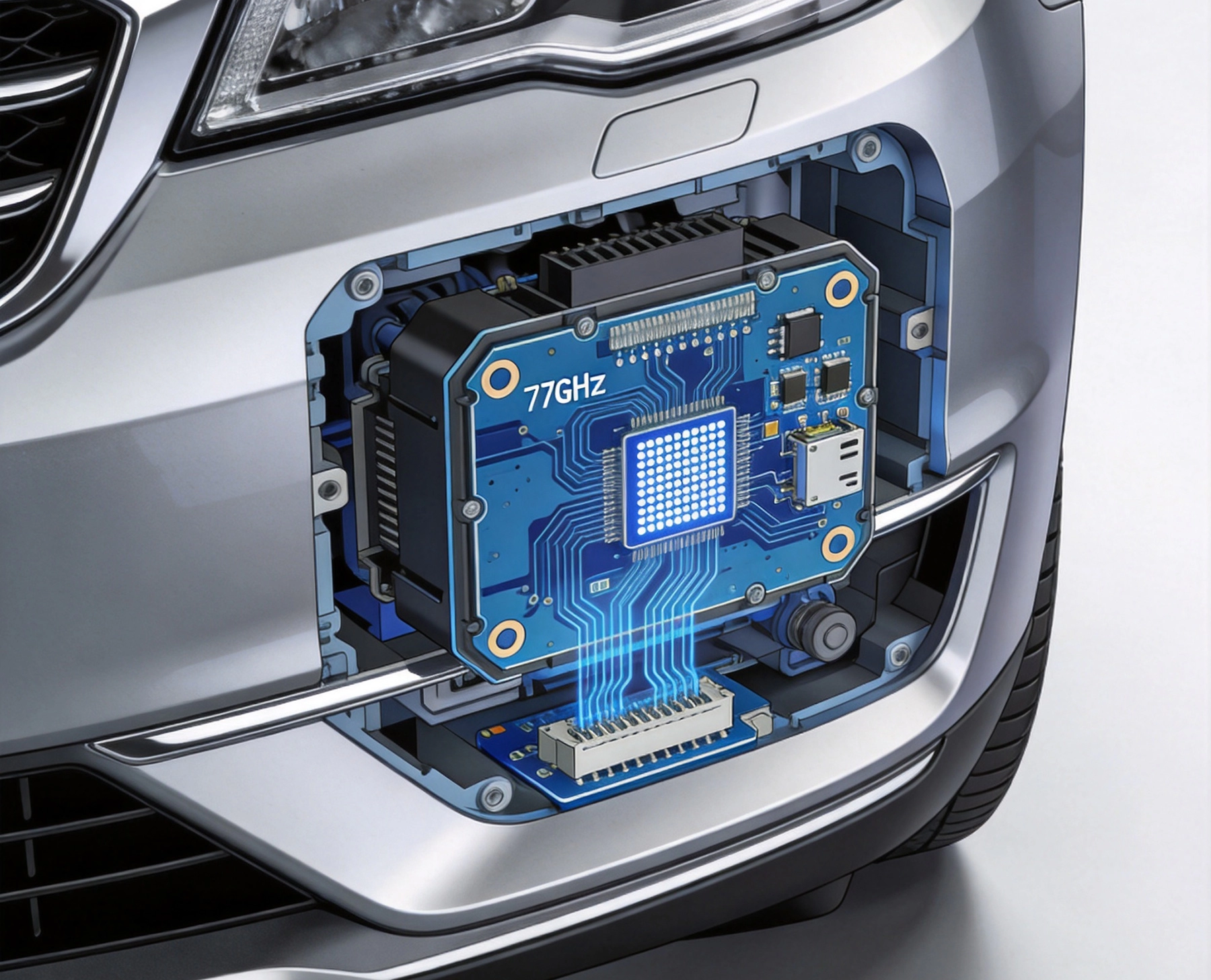
Modern Automotive Radar operates in the 76-81 GHz band allocated internationally for vehicle safety applications. This frequency range offers an optimal balance between antenna size, range resolution, and atmospheric attenuation. Higher frequencies enable smaller antennas with narrower beamwidths, improving angular resolution for distinguishing adjacent objects. The short wavelengths at 77 GHz, approximately 3.9 millimeters, allow patch antennas to be integrated directly onto the PCB substrate.
The transition from 24 GHz to 77 GHz radar has reshaped the automotive safety landscape. Older 24 GHz ultra-wideband radar provided adequate performance for basic functions but lacked the resolution for advanced applications. 77 GHz systems offer four times the bandwidth, enabling range resolution of a few centimeters versus tens of centimeters at lower frequencies. This improvement makes possible features like corner radar for blind spot monitoring and precise object classification for autonomous emergency braking.
At 77 GHz, even microscopic manufacturing variations affect electrical performance. Trace width variations of a few microns alter Characteristic Impedance significantly. Dielectric Constant variations from material inhomogeneity cause phase errors across the antenna array. Via stub effects that are negligible at lower frequencies become limiting factors for radar performance. These challenges require manufacturing tolerances measured in microns rather than mils.
Insertion Loss becomes critical when every decibel of signal matters. Losses in Transmission Lines, connectors, and transitions directly reduce radar range and sensitivity. A 1 dB loss increase might reduce detection range by 10% or more, potentially missing obstacles at critical moments. Minimizing loss requires low-loss Dielectric Materials, precise Impedance Control, and careful RF transition design.
Material selection fundamentally determines what performance is achievable from a Radar Pcb. Standard Fr-4 materials introduce excessive loss and unacceptable dielectric variation at 77 GHz, making high-performance substrates essential. The industry has converged on several material families that balance electrical performance, manufacturing capability, and cost for automotive volume production.
PTFE-based materials offer the lowest loss at millimeter-wave frequencies. Rogers RT/duroid 5880 and similar products achieve dissipation factors below 0.001 at 77 GHz, minimizing signal attenuation. However, PTFE materials present manufacturing challenges including poor adhesion, difficult drilling, and higher costs. These trade-offs are acceptable for the antenna substrate where loss directly impacts radar performance.
The automotive industry has largely adopted hydrocarbon ceramic materials as the optimal balance for radar applications. Rogers Ro4350b and Isola Astra MT77 represent this category, offering loss tangents around 0.003-0.004 at 77 GHz. These materials process similarly to standard Fr-4, enabling established manufacturing techniques while providing significantly better electrical performance.
Modified epoxy systems like Panasonic Megtron 6 offer attractive loss characteristics with excellent manufacturing compatibility. These materials bond well with standard prepregs, simplifying stack-up construction for multilayer radar boards. Their thermal conductivity benefits thermal management in radar modules where power amplifiers generate significant heat.
Automotive radar requires material properties to remain stable over the vehicle lifetime. Thermal coefficient of Dielectric Constant (TCDk) quantifies how much the dielectric constant changes with temperature. Materials with low TCDk ensure that radar calibration remains valid across operating temperature ranges from -40°C to +125°C. Specifications typically require TCDk below 50 ppm/°C for radar applications.
Dimensional stability ensures that manufacturing variations do not compromise antenna pattern consistency. Material data sheets specify z-axis expansion coefficients, glass transition temperatures, and moisture absorption that affect board dimensions during processing and in service. Material qualification testing verifies that production lots meet the same specifications as qualification samples.
Radar Signal Integrity depends on precise Impedance Matching throughout the RF signal path. Characteristic Impedance variations cause Signal Reflection that reduces transmitted power and creates ghosts in received signals. Maintaining impedance within tight tolerances across manufacturing variations and environmental conditions demands meticulous design and process control.
The characteristic impedance of a Transmission Line depends on trace geometry and dielectric constant. At 77 GHz, trace dimensions are comparable to skin depth, making surface roughness a significant factor. The effective dielectric constant for microstrip circuits depends on both substrate properties and trace geometry, requiring simultaneous control of both factors.
Typical 50-ohm microstrip traces on radar boards measure 0.3-0.5 mm width depending on substrate thickness and dielectric constant. Manufacturing tolerances of ±0.02 mm on trace width translate to impedance variations of 1-2 ohms, which is acceptable for most applications. However, achieving these tolerances requires controlled etching processes and regular impedance verification.
Stack-up design determines substrate thickness that affects trace geometry. Common thicknesses for radar applications range from 0.1 mm to 0.5 mm depending on frequency and board requirements. Thinner substrates enable smaller traces but increase conductor losses due to surface roughness effects. Design optimization balances these competing requirements based on specific application needs.
Signal return path quality significantly affects Transmission Line performance. Gaps, slots, or discontinuities in the reference plane force return currents to detour around obstacles, creating inductance and radiation. For millimeter-wave circuits, these effects are severe enough to make continuous reference planes essentially mandatory for reliable performance.
Via stitching provides AC ground connections between reference planes on multilayer boards. Via spacing must be sufficiently dense to present a solid ground at 77 GHz, typically requiring vias spaced less than 1/20 wavelength apart. This spacing translates to via pitch of approximately 0.2 mm or less, creating manufacturing challenges for via formation and placement.
The antenna represents the most critical and challenging element of Automotive Radar Pcb design. Patch antenna arrays etched directly onto the PCB substrate must achieve consistent gain, pattern, and beamwidth across production volumes. Antenna performance determines radar field of view, range, and angular resolution, making antenna yield a primary driver of overall radar module cost.
Series-fed patch arrays provide the narrow elevation beamwidth needed for horizon detection. Corporate-fed networks distribute power uniformly to each element while maintaining phase alignment. The feed network must match impedance across all array elements to prevent pattern distortion from element mismatch. Standing waves in the feed network create amplitude and phase ripple across the array aperture.
Patch antenna dimensions are determined by wavelength within the substrate, requiring micron-level tolerances for resonant frequency accuracy. A patch designed for 77 GHz might have dimensions near 1 mm by 1 mm, with tolerance requirements of ±0.01 mm or tighter. This precision demands photolithography processes with resolution and registration capabilities well beyond standard Pcb Manufacturing.
Metal thickness affects antenna efficiency and bandwidth. Skin depth at 77 GHz is approximately 0.8 microns for copper, meaning that even 18-micron copper cladding far exceeds requirements. However, thicker metallization reduces conductor losses and improves Q-factor for narrowband applications. The tradeoff between loss and bandwidth determines optimal thickness for each design.
Automotive radar sensors are mounted behind plastic radomes that protect the antenna from environmental exposure while allowing millimeter-wave signals to pass with minimal loss. These radomes must be designed to avoid reflections that could interfere with the antenna pattern. Water absorption in radome materials can shift resonance frequencies and attenuate signals during rain or humidity exposure.
Internal moisture protection for the Pcb Assembly includes conformal coating and sealing that prevent water vapor from reaching the antenna and Rf Circuits. These coatings must be transparent to 77 GHz signals, limiting material choices to those with appropriate dielectric properties. Thin acrylic coatings typically add less than 0.1 dB Insertion Loss while providing essential protection against condensation.
Radar transceivers include power amplifiers that generate significant heat during operation. Modern 77 GHz radar chips with integrated transmitters may output 10-15 dBm per channel, with multiple channels combined in the feed network. The antenna substrate absorbs some heat, while additional thermal management paths through the PCB ensure junction temperatures remain within safe operating limits.
Thermal vias connect heat-generating components to metal heat spreaders or the sensor housing. These vias must not interfere with RF signal paths, requiring careful layout that separates thermal and Rf Design domains. Thermal interface materials between the PCB and heatsinking surfaces provide low-resistance heat transfer paths that prevent hot spots near power devices.
Automotive radar experiences temperature extremes that stress solder joints, component interfaces, and Pcb Materials. A sensor mounted behind a front bumper might cycle from -40°C during winter cold soak to +85°C or higher during summer operation. These cycles accumulate over the vehicle lifetime, potentially exceeding 1,000 temperature excursions that can fatigue solder joints and delaminate PCB layers.
Lead-free solder alloys required by environmental regulations exhibit higher stiffness than tin-lead solder, creating greater stress at component interfaces. These materials are more susceptible to crack propagation under thermal cycling. Higher tin content solders like SAC305 provide reasonable thermal fatigue resistance, but some manufacturers specify premium alloys with small additions of elements like manganese or nickel to improve fatigue life.
Assembling radar PCBs demands process capabilities that exceed standard Smt manufacturing. The combination of fine-pitch components, RF transitions, and high-frequency materials creates assembly challenges requiring specialized equipment and expertise. Many standard contract manufacturers cannot achieve the tolerances required for 77 GHz radar production.
Component Placement for 77 GHz radar modules typically includes BGAs with 0.4 mm or finer pitch, discrete components as small as 01005 size, and specialized RF components like surface launch connectors. Each component type presents distinct assembly challenges that must be addressed through process optimization and quality verification.
Stencil design for fine-pitch components follows the same principles as other high-density assembly, with aperture dimensions carefully matched to pad size for optimal paste release. Electroformed nickel stencils with nanocoatings provide the best release characteristics for 0.4 mm pitch BGAs. Stencil thickness selection balances solder volume requirements against bridging risk, with 80-100 micron thickness typical for radar assemblies.
Reflow profile optimization ensures complete wetting without excessive intermetallic formation that creates brittle joints. For high-frequency assemblies, nitrogen atmosphere reflow reduces oxidation and improves wetting consistency. Peak temperatures must be high enough to achieve reliable solder joints without damaging substrates or components, requiring careful profiling for each specific board construction.
RF transitions between the PCB and external connectors must maintain Signal Integrity through the connection interface. Edge-launch coaxial connectors provide clean transitions with minimal discontinuity when properly installed. The board edge preparation, connector placement, and solder application all affect transition quality.
Connector-to-board interface inspection using vector network analysis verifies that transitions meet return loss specifications. Reflections from imperfect transitions reduce available signal power and create standing waves that distort the antenna pattern. Production testing with Vna or time-domain reflectometry screens assemblies for transition defects before they affect radar performance.
Automotive radar modules must meet stringent quality and reliability standards established by the automotive industry. The AEC-Q series of standards defines qualification requirements for automotive electronic components. Pcb Assembly must comply with these standards to be used in safety-critical applications where failure could cause accidents or injuries.
AEC-Q100 covers integrated circuits and includes requirements for electrical verification, stress testing, and failure analysis. AEC-Q200 addresses passive components with their own set of qualification tests. For the PCB assembly itself, the IPC standards provide baseline workmanship criteria that are supplemented by automotive-specific requirements from customers and OEM specifications.
Automotive qualification includes temperature cycling between -40°C and +125°C for 1,000 cycles or more, representing accelerated aging equivalent to years of field operation. Highly accelerated stress testing (HAST) applies temperature, humidity, and bias simultaneously to accelerate moisture-related failures. Mechanical testing covers vibration, shock, and board flex to verify assembly robustness.
ESD sensitivity classification determines handling requirements for components and assemblies. Radar modules typically include components classified as ESD sensitive, requiring appropriate precautions throughout manufacturing and assembly. ESD-safe workstations, ionizers, and proper grounding prevent damage from electrostatic discharge during handling.
Automotive quality systems require documented process controls and complete traceability. Statistical process control monitors key parameters including solder paste volume, placement accuracy, and reflow temperatures. Out-of-control conditions trigger immediate investigation and corrective action before production continues.
Lot traceability connects finished assemblies to their constituent components, materials, and manufacturing process records. This traceability enables investigation when field failures occur and supports recall actions if necessary. Automotive customers typically require traceability documentation with each shipment, increasing administrative overhead compared to non-automotive applications.
Radar module testing spans multiple levels from component verification through system integration. Each testing stage catches defects at the most cost-effective point before value-adding processing on potentially defective assemblies. The combination of electrical test, visual inspection, and functional verification provides confidence that assemblies will perform reliably in service.
Automated optical inspection verifies Component Placement and solder joint quality before reflow. X-ray Inspection examines hidden joints under BGAs and other area-array packages. For RF assemblies, these inspections are supplemented by electrical testing that verifies RF performance including insertion loss, return loss, and phase matching across the signal path.
Vna Testing measures S-parameters that quantify RF performance including reflection and transmission characteristics. Return loss or VSWR measurements reveal impedance mismatches that cause Signal Reflection. Insertion loss measurements verify that signal paths meet loss budgets. Phase measurements confirm that path lengths match design targets for proper beamforming.
Production Vna Testing faces challenges of throughput versus measurement accuracy. Modern Vna systems can measure key parameters in seconds per device, enabling production-line testing with minimal throughput impact. Calibration standards and fixture compensation ensure measurement accuracy despite variations in test equipment and connections.
Final assembly testing validates complete radar functionality including transmit power, receiver sensitivity, and antenna pattern. Anechoic chambers provide controlled environments for range and pattern measurements without interference from reflections. Free-space measurements verify detection range, angular resolution, and discrimination capability against test targets.
Corner reflector targets of known radar cross-section calibrate range measurement accuracy. Multiple target scenarios verify discrimination between adjacent objects. Environmental testing places operational radar modules in thermal chambers to verify continued performance across temperature extremes.
Automotive radar module costs include substrate materials, assembly processing, testing, and yield losses. High-performance materials like Rogers PTFE products cost significantly more than standard FR-4. The specialized manufacturing equipment and processes required for millimeter-wave assembly add further cost. These cost drivers push manufacturers toward yield optimization that maximizes output from expensive processing steps.
First-pass yield directly affects cost per good unit. Defects detected late in manufacturing, particularly after expensive testing or coating steps, waste substantial value. Implementing defect detection early, combined with root cause analysis that prevents recurrence, improves yields over production lifecycles.
Dfm collaboration between radar designers and assembly specialists identifies potential manufacturing issues early in the design phase. Panel efficiency, component accessibility, and test point placement all affect manufacturing cost and yield. Early engagement allows design modifications that improve producibility before tooling commitments lock in suboptimal approaches.
Standardization across product generations reduces learning curve costs when new variants enter production. Common stack-up constructions, panel sizes, and assembly sequences enable knowledge transfer from one product to the next. This standardization reduces qualification effort and improves yields on derivative products.
high frequency PCB assembly for automotive radar demands precision and reliability that push manufacturing capabilities to their limits. The combination of 77 GHz operation, automotive qualification requirements, and safety-critical application creates an assembly environment unlike any other in electronics manufacturing.
Success in this market requires investment in specialized materials, equipment, and expertise that only a handful of manufacturers worldwide can provide. The automotive industry's confidence in radar-based safety features depends on this manufacturing expertise delivering reliable assemblies year after year.
For engineers specifying radar modules and manufacturers considering automotive opportunities, understanding these assembly requirements clarifies the challenges and investments necessary to compete. The stakes are high, with human safety depending on radar reliability in every vehicle that leaves the assembly line.

Ensuring Signal Integrity During High Frequency PCB Assembly ProcessesJuly/15/2026

Avoiding Soldering Defects in High Frequency PCB Assembly for RF ApplicationsSeptember/11/2026

Why Component Placement is Critical in High Frequency PCB AssemblyJune/25/2026
SMT vs. THT: Assembly Techniques for High Frequency PCBsJuly/03/2026
High Frequency PCB Assembly Best Practices for 5G and RF ModulesJune/08/2026
The Challenges of High Frequency PCB Assembly: Handling Sensitive ComponentsMay/29/2026

How to Select a Turnkey High Frequency PCB Assembly PartnerAugust/06/2026

How High Frequency PCB Applications are Powering the AI Server RevolutionAugust/03/2026