Open Nav

Automotive Radar sits at a demanding intersection: the signals operate at 77-79 GHz, where every picosecond of propagation delay and every fraction of a decibel of Insertion Loss matters, while the physical environment is among the harshest in electronics — temperature swings from -40°C to +105°C, vibration, humidity, thermal cycling over a 15-year vehicle lifetime, and the relentless cost pressure of automotive production. The PCB material chosen for the radar module must satisfy both sides of this equation: the speed demanded by millimeter-wave Signal Integrity and the durability demanded by automotive qualification standards.
This article examines the high frequency PCB materials used in Automotive Radar, how their dielectric properties affect radar performance, what durability requirements automotive specifications impose, and how to select materials that deliver both speed and reliability at a cost the automotive industry can accept.
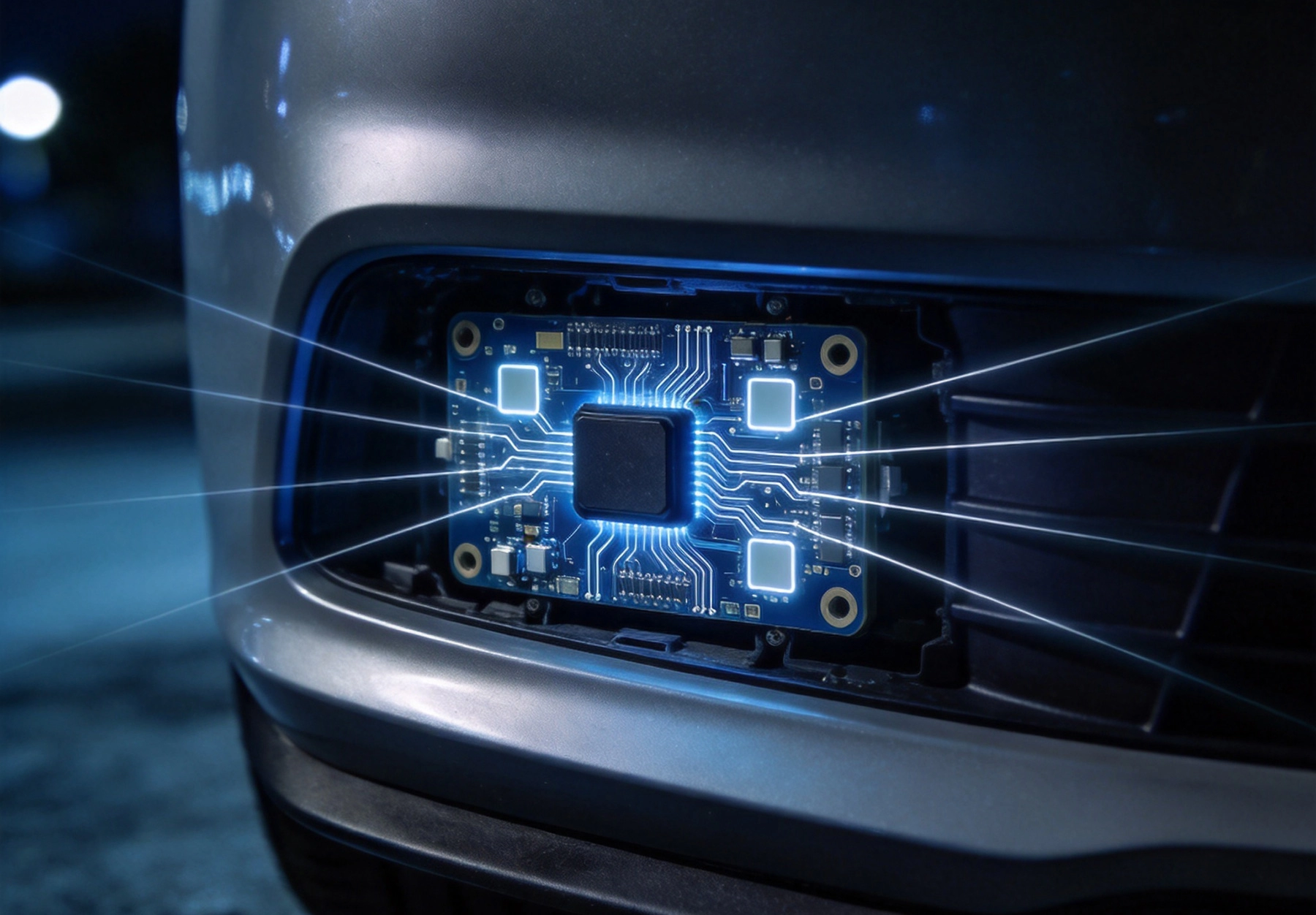
Modern automotive radar systems operate in the 76-81 GHz band, with the majority of production designs centered on 77-79 GHz. At these frequencies, the wavelength in free space is approximately 3.8-3.9 mm — and within the PCB dielectric, it is even shorter (about 1.9-2.2 mm for typical substrate materials). This has profound implications for Pcb Material Selection.
At millimeter-wave frequencies, the Dielectric Constant (Dk) and Dissipation Factor (Df) of the PCB substrate directly determine three critical performance parameters:
The radar module's PCB typically includes patch antenna arrays, feed networks (corporate feeds or series feeds), power distribution networks, and the RF front-end circuitry around the radar transceiver IC. The feed network is often the most loss-sensitive element — it distributes the RF signal from the transceiver to multiple antenna elements, and every decibel of loss in the feed reduces the effective isotropic radiated power (EIRP) and degrades the receive signal-to-noise ratio.
The Pcb Materials relevant to automotive radar span a range from standard FR4 (unsuitable for 77 GHz RF paths but sometimes used for non-RF layers) to specialized Ptfe-based and hydrocarbon ceramic laminates. Here is how the leading candidates compare:
Automotive radar modules are typically mounted in the vehicle front end — behind the front grille, in the bumper, or on the radiator support structure. This location exposes the PCB to environmental extremes that most commercial RF designs never face.
Automotive under-hood environments experience wide temperature cycling. A cold start at -40°C followed by engine warm-up to +85°C or higher, repeated thousands of times over the vehicle's life. Each cycle causes differential expansion between the copper, the dielectric, and any component attached to the board. The critical material parameter is the coefficient of thermal expansion (CTE):
Humidity exposure is a significant concern for high-frequency materials. PTFE-based laminates are inherently hydrophobic and absorb very little moisture (typically less than 0.02 percent), which is an advantage for maintaining stable Dk and Df in humid environments. Hydrocarbon ceramic laminates absorb more moisture (0.05-0.15 percent) but still far less than standard FR4 (0.1-0.3 percent).
Moisture absorption affects high-frequency performance in two ways: absorbed water increases the effective Dk (water's Dk ≈ 80) and increases Df (water is lossy at microwave frequencies). For a radar module that may be exposed to condensation during cold starts after humid storage, the material's moisture absorption characteristics directly affect the consistency of the radar calibration.
Vehicle vibration — from road surfaces, engine harmonics, and chassis resonance — subjects the Radar Pcb to continuous mechanical stress. The material's flexural modulus (stiffness) affects how the board responds:
For automotive radar modules, the PCB is typically mounted to a rigid aluminum housing that provides mechanical support and serves as a heatsink. This mitigates the vibration concern somewhat, but the material's mechanical properties still factor into long-term reliability, especially for antenna structures that are not supported by the housing.
Automotive electronic components are qualified to AEC-Q200, which defines a suite of stress tests including temperature cycling (1,000 cycles, -40°C to +125°C), high-temperature operating life, moisture resistance, mechanical shock, and vibration. While AEC-Q200 is formally a component-level specification, the PCB substrate material must be capable of supporting the assembled module through these tests. Material selection directly determines whether the radar module can pass AEC-Q200 qualification.
The core tension in automotive radar Pcb Material Selection is that the materials with the best high-frequency electrical properties (PTFE-based, very low Df) have the worst mechanical and thermal reliability characteristics, while the materials with the best durability (hydrocarbon ceramic, FR4-compatible) have higher Df that degrades radar performance.
Use a low-Df material (RO3003 or similar) for all layers. This maximizes RF performance but introduces reliability risk from the material's high CTE and mechanical softness. Via reliability in multilayer constructions is a particular concern — PTFE-based materials with high Z-axis CTE can experience via barrel cracking during thermal cycling.
This approach is used in some premium automotive radar designs where performance is prioritized over cost and where extensive reliability testing has validated the construction.
Use low-loss material only on the layers that carry RF signals, with standard or mid-loss material on the remaining layers. This is the most common approach in production automotive radar modules:
The hybrid approach delivers low insertion loss on the RF paths while maintaining the mechanical and thermal reliability of FR4 on the structural layers. It also reduces material cost — Low-loss Laminate is used only where needed, not on every layer.
Use a mid-loss material (RO4350B, RO4835, or Megtron 6) for all layers. This simplifies manufacturing (single material system, no hybrid bonding challenges) and provides better reliability than PTFE-based materials, at the cost of higher insertion loss on RF paths.
Whether this approach is acceptable depends on the radar architecture. For short-range radar (SRR) modules operating at lower power, the additional insertion loss of mid-loss material may be tolerable within the link budget. For long-range radar (LRR) modules that must detect targets at 200+ meters, every decibel of loss matters and the all-mid-loss approach may not provide sufficient range performance.
At millimeter-wave frequencies, conductor loss can equal or exceed dielectric loss, making copper foil type as important as laminate selection. The key parameter is the surface roughness of the copper foil at the dielectric interface.
At 77 GHz, the skin depth in copper is approximately 0.23 µm. Current flows in an extremely thin layer at the copper surface. If the copper surface is rough (with peaks and valleys on the order of the skin depth or larger), the effective current path length increases — the current must follow the contours of the rough surface rather than a straight line. This increases the effective resistance and therefore the conductor loss.
The impact is dramatic: conductor loss at 77 GHz on standard electrodeposited (ED) copper (roughness Ra ≈ 2-3 µm) can be 2-3× higher than on very low-profile (VLP) copper (Ra ≈ 0.4-0.6 µm). For a radar feed network with 20-30 mm of total trace length, this translates to 1-2 dB of additional insertion loss from copper roughness alone.
The trade-off with smoother copper is adhesion. Rough copper provides mechanical anchor points that bond strongly to the laminate resin. Smooth copper has less surface area for bonding and is more susceptible to delamination under thermal cycling — exactly the stress automotive environments impose. Reverse-treated foil (RTF) and low-profile (LP) copper are the practical choices that balance conductor loss and adhesion reliability for automotive radar.
The relationship between PCB insertion loss and radar range is direct and unforgiving. In a radar link budget, PCB insertion loss appears twice — once in the transmit path (reducing EIRP) and once in the receive path (reducing signal level before the LNA). Each decibel of insertion loss in the PCB reduces the received signal-to-noise ratio by 2 dB, which translates to a range reduction of approximately 10 percent per 2 dB (for a radar with range proportional to the fourth root of SNR).
Consider a typical 77 GHz radar module with a 4-element transmit array and a 4-element receive array. The corporate feed network on each array has approximately 15-20 mm of total Microstrip or stripline trace length, plus junction discontinuities at power dividers.
The difference between RO3003 and RO4350B is approximately 2 dB in the total insertion loss budget, which translates to roughly a 5-10 percent difference in radar detection range. For long-range radar targeting 200+ meters, this difference is significant. For corner radar or short-range applications with 30-50 meter range requirements, the RO4350B option may be fully acceptable.
The choice of high-frequency material also affects the manufacturing process and cost of the Radar Pcb.
Yes — for the non-RF portions of the module. The digital control interface, power supply regulation, processor, and memory can all be routed on FR4 layers without any performance impact, because these signals are at frequencies where FR4 loss is acceptable. The key is to keep the RF signal path — from the transceiver IC through the feed network to the antenna elements — on low-loss material. A hybrid stack-up that uses FR4 for digital/power layers and low-loss material for RF layers is the standard production approach.
Yes, with proper design and manufacturing. RO4350B has been used in production automotive radar modules for several years and has demonstrated reliability through AEC-Q200 qualification testing. The material's CTE is reasonably matched to copper (X/Y CTE ≈ 14 ppm/°C), and its Z-axis CTE is low enough for reliable via structures. RO4835, which is specifically designed for improved thermal stability, is an even safer choice for new designs.
Moisture absorbed into the PCB dielectric increases Dk and Df, shifting the center frequency of antenna elements and increasing insertion loss. For a radar module calibrated at the factory under controlled conditions, subsequent moisture absorption in the field can shift the radar performance enough to degrade detection accuracy — particularly for long-range applications where every decibel and every degree of phasing matters. PTFE-based materials, with their near-zero moisture absorption, are inherently more calibration-stable than hydrocarbon ceramic or FR4 materials. For hydrocarbon ceramic designs, Conformal Coating and sealed housings help limit moisture exposure.
RO3003 (PTFE-ceramic) is typically 30-50 percent more expensive than RO4350B (hydrocarbon ceramic) on a per-sheet basis. The total cost difference for the radar PCB also includes the processing premium for PTFE — special drilling, plating treatment, and lamination — which can add another 20-30 percent to the fabrication cost. On the other hand, RO3003's lower insertion loss may allow the use of a lower-power transceiver IC or a smaller antenna array, potentially saving more at the system level than the material adds at the board level. The total system cost comparison requires analysis beyond just the laminate price.
Yes. Several laminate manufacturers are developing next-generation materials specifically for 77-81 GHz automotive radar that aim to combine PTFE-level loss with FR4-level processability and reliability. These materials use novel resin systems and filler technologies to achieve Df values below 0.002 with CTE characteristics close to FR4. While most are still in qualification or early production, they represent a significant evolution that could simplify the material selection trade-off in future radar designs.
Selecting the right PCB material for automotive radar is a multi-dimensional optimization problem where no single material is optimal on every axis. PTFE-based laminates offer the lowest loss for maximum radar range but challenge reliability and manufacturing. Hydrocarbon ceramic materials offer FR4-compatible processing and good reliability with moderate loss that is sufficient for many applications. Hybrid stack-ups provide the best practical balance for production designs. The key to a successful material selection is understanding your radar's specific link budget requirements, the thermal and mechanical environment the module will face, the manufacturing capabilities of your fabricator, and the total system cost — not just the laminate cost. With this understanding, you can make an informed choice that delivers both the speed your radar needs and the durability your automotive customer demands.
Contact us to discuss your requirements
The Impact of Copper Foil Type on High Frequency PCB Materials PerformanceSeptember/16/2026
How Dielectric Constant (Dk) and Loss Factor (Df) Affect High Frequency PCB MaterialsJuly/18/2026
Understanding Thermal Stability in High Frequency PCB MaterialsAugust/10/2026

Top 5 High Frequency PCB Materials for 5G Base Station ApplicationsJuly/30/2026
Cost vs. Performance: Selecting Budget-Friendly High Frequency PCB MaterialsSeptember/04/2026
Emerging Trends in High Frequency PCB Materials for Next-Gen CommunicationOctober/10/2026
Rogers vs. FR4: Choosing the Right High Frequency PCB MaterialsJune/12/2026
Choosing the Right High Frequency PCB MaterialsMay/29/2026