Open Nav

RF and microwave circuit designers face material challenges that disappear in digital applications. Signal losses, impedance drift, and frequency-dependent behavior stem as much from substrate choices as from component selection or layout optimization. Standard Fr-4 epoxy composites serve digital circuits adequately but introduce performance degradation at frequencies above a few gigahertz. Rogers Corporation and Ptfe-based laminates address these limitations through precisely controlled dielectric properties enabling consistent performance into millimeter-wave frequencies. Understanding these materials and their fabrication requirements determines whether your high-frequency design achieves its performance targets or merely approximates them.
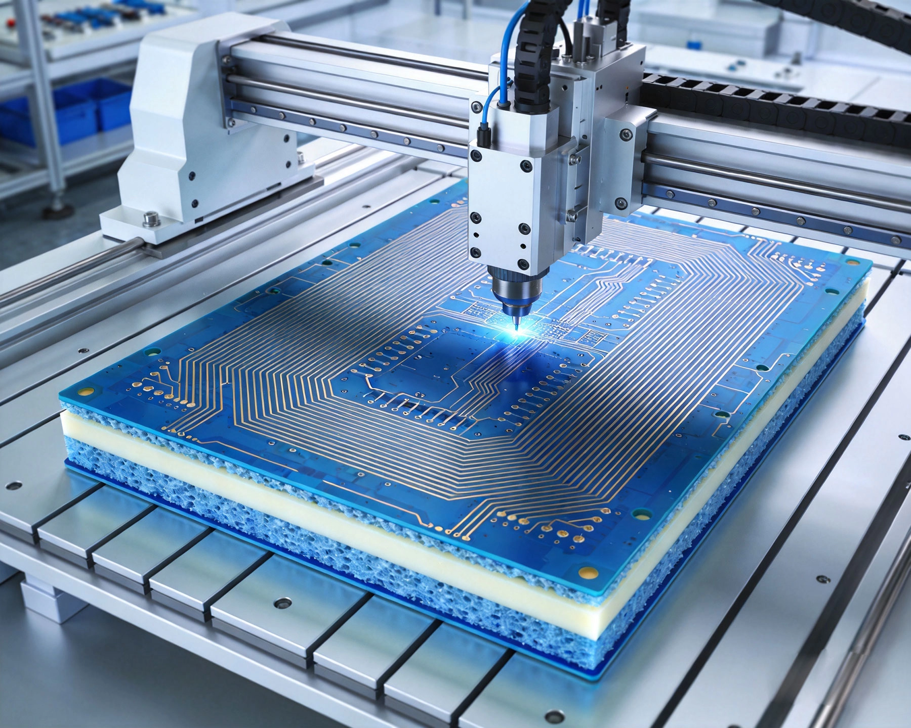
Fr-4 contains woven glass fibers embedded in epoxy resin, creating heterogeneous dielectric structures with inconsistent electrical properties. The glass weave creates variations in effective Dielectric Constant across the substrate, causing velocity variations and impedance discontinuities. At 5GHz and above, these variations create measurable performance degradation that FR-4 datasheets never acknowledge.
Dissipation Factor—sometimes called loss tangent—measures how much RF energy converts to heat during signal propagation. FR-4 Dissipation Factor ranges from 0.02 at 1MHz to substantially higher values as frequency increases. This means significant signal attenuation in high-frequency applications where maintaining Signal Integrity matters critically.
A 10dB loss budget sounds manageable until you calculate absolute power requirements and thermal considerations. In receive chains or low-power Rf Circuits, dissipation factor differences between FR-4 and specialized materials determine whether designs meet sensitivity specifications or fall short inexplicably.
Epoxy-based materials absorb moisture from humid environments, changing their dielectric properties as water displaces resin volume. RF signals respond to these changes through frequency-dependent absorption and impedance shifts. Outdoor equipment, aerospace systems, and maritime applications all experience moisture exposure that FR-4 designs cannot ignore.
The Dielectric Constant of water—approximately 80 at RF frequencies—far exceeds that of dry epoxy—approximately 4.2. Even small moisture uptake dramatically affects effective dielectric constant and loss characteristics. Designs requiring stable performance over environmental ranges cannot rely on moisture-sensitive substrates.
Ptfe—polytetrafluoroethylene, the material making Teflon non-stick coatings—provides excellent electrical properties alongside chemical inertness and moisture resistance. Pure PTFE presents challenges for PCB Fabrication, so manufacturers developed modified formulations and ceramic-filled variants addressing these limitations.
PTFE offers stable dielectric constant approximately 2.1 across wide frequency ranges with extremely low dissipation factor below 0.002. Moisture absorption approaches zero—less than 0.01% by weight—providing environmental stability impossible with organic substrates. These properties make PTFE the baseline for high-frequency applications from L-band through Ku-band.
However, pure PTFE presents manufacturing challenges. The material softens at soldering temperatures, causing dimensional instability during assembly. PTFE surfaces resist adhesion to copper, complicating conductor formation. Additives and filler materials address these issues while preserving electrical performance.
Rogers RT/duroid laminates combine PTFE with ceramic fillers achieving dielectric constants ranging from 2.1 to 10.2 while maintaining low loss characteristics. Ceramic loading increases rigidity and improves thermal stability, enabling processing more similar to conventional materials while preserving high-frequency performance.
Common Rogers materials include RT/duroid 5870 (dielectric constant 2.33) using glass microfiber reinforcement, RT/duroid 5880 (dielectric constant 2.2) with reduced dielectric loss, and RT/duroid 6006 (dielectric constant 6.15) for applications requiring higher Impedance Control and capacitive coupling. Each formulation targets specific application requirements within the high-frequency spectrum.
Rogers RO4000 series materials use hydrocarbon ceramic construction offering performance approaching PTFE at lower cost. RO4350B with dielectric constant 3.48 and RO4003C with 3.38 represent popular choices balancing electrical performance, manufacturing compatibility, and economic considerations.
These materials process more like standard FR-4 through standard plated-through-hole technology while maintaining much better high-frequency properties. The trade-off involves higher dissipation factor than pure PTFE—approximately 0.0037 versus 0.001 for RT/duroid—still far better than FR-4 but measurably different for loss-critical applications.
Designing circuits for specialized substrates requires different approaches than standard PCB design. Material properties vary more with frequency, temperature, and thickness than FR-4, demanding careful consideration of these variables during design.
PTFE and ceramic-filled materials exhibit tighter dielectric constant tolerances than FR-4—typically ±0.02 for precision materials versus ±0.2 or looser for standard epoxies. This consistency enables more predictable Impedance Control and better matching network performance across production boards.
However, dielectric constant varies with frequency. Manufacturers specify values at specific frequencies—often 10GHz for microwave laminates—while designs operate elsewhere. Understanding this frequency dependence and accounting for it in simulations and calculations becomes important for wideband applications.
PTFE expands and contracts more with temperature than glass-filled epoxies. The temperature coefficient of dielectric constant (TCDk) quantifies these changes. Rogers materials specify positive TCDk values—dielectric constant increases with temperature—which affects frequency stability in temperature-varying environments.
Some applications benefit from temperature-compensating designs using materials with negative TCDk. Rogers TMM series combines hydrocarbon ceramics with specific temperature characteristics enabling compensation network designs for stable frequency performance across environmental ranges.
PTFE materials expand more than copper in the z-axis during heating, creating concerns for plated-through-hole reliability. Through-holes experience stress during thermal cycling that FR-4's lower expansion mismatch doesn't create. Designs requiring PTH on PTFE substrates need attention to hole wall thickness and plating quality.
Thermal expansion in the x-y plane also exceeds FR-4, potentially causing surface mount solder joint stress under thermal cycling. Components with low standoff heights experience fatigue more rapidly on PTFE substrates than on rigid FR-4. Drop-test performance may suffer for portable equipment using PTFE boards.
PTFE-based materials demand modified fabrication approaches that challenge shops accustomed to standard PCB processing. Understanding these requirements helps avoid manufacturing surprises and enables productive conversation with fabrication partners.
PTFE surfaces require plasma or chemical treatment to improve copper adhesion. Sodium etchant removes surface fluorine atoms, creating chemically active surfaces for improved bonding. This step—unnecessary for FR-4—adds process complexity and cost but remains essential for reliable conductor adhesion.
Material handling requires care to avoid contamination. PTFE absorbs oils and chemicals that migrate into the dielectric and affect electrical properties. Shops switching from FR-4 to PTFE must establish separate processing lines or implement thorough cleaning protocols between different material types.
PTFE's softness causes different tooling requirements than glass-reinforced materials. Standard carbide bits may smear PTFE rather than cutting cleanly, requiring specialized tooling with sharper angles and different flute geometries. Feed rates and spindle speeds require optimization for clean cuts without burr formation.
Laser ablation provides alternative routing for complex shapes, particularly useful for PTFE materials where mechanical routing creates challenges. CO2 lasers cut PTFE cleanly without the heat-affected zones that cause problems in other materials. This capability enables geometries impractical with mechanical routing.
PTFE requires specialized desmear and activation processes before electroless copper plating. Standard FR-4 desmear chemistry doesn't reliably remove PTFE smear from drilled holes, preventing adequate copper adhesion. Plasma etching or specialized chemical treatments activate PTFE surfaces for plating adhesion.
Via filling and blind/buried via processing on PTFE substrates demand careful process control. The low modulus of PTFE allows more flexing during thermal cycling, potentially fatiguing plated via barrels. Designs should specify appropriate minimum annular ring sizes and barrel thickness to ensure reliable interconnections.
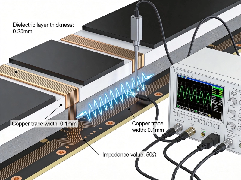
High-frequency circuits require Controlled Impedance traces more precisely than digital designs. PTFE substrate tolerances contribute to impedance variation—thickness tolerances of ±0.001 inches or tighter affect impedance directly. Fabricators must control dielectric thickness, copper roughness, and trace width precisely to achieve ±5% impedance tolerances.
Test coupons on production panels verify impedance performance, but coupon-to-product correlation may vary with trace geometry and proximity effects. Designs requiring tight impedance control should specify impedance testing on actual product traces rather than relying solely on coupon measurements.
Choosing among available high-frequency materials requires matching application requirements to material capabilities. Over-specifying material requirements wastes cost while under-specifying compromises performance.
Applications from DC through X-band (up to 12GHz) function adequately with RO4000 series hydrocarbon ceramic materials. The cost advantage over PTFE makes these materials attractive for commercial applications where ultimate loss performance isn't critical. Wi-Fi, cellular infrastructure, and Automotive Radar in 24-77GHz ranges increasingly use these materials as technology matures.
Aerospace and defense applications requiring Ku-band through Ka-band (12-40GHz) typically specify PTFE materials for lowest dissipation factor. Satellite Communications, military radar, and instrument landing systems need the performance margin that PTFE provides. Cost sensitivity is lower in these markets, enabling premium material investments.
High-power RF applications heat substrates through dissipation factor losses. Power amplifier designs require materials with both low dissipation factor and adequate thermal conductivity to remove generated heat. Rogers TMM series offers thermal conductivity approximately 0.7 W/mK compared to 0.3 W/mK for most PTFE materials, providing better heat spreading.
p>Thermal Management becomes critical in high-power applications. Even low dissipation factors create meaningful absolute loss at kilowatt power levels common in broadcast and radar transmitters. Material selection for these applications must consider both electrical loss and thermal performance.Material costs vary enormously—from approximately $2-5/square foot for RO4350B to $50-100/square foot for premium RT/duroid grades. Panel utilization efficiency, fabrication complexity, and yield differences multiply material cost variations into larger total cost impacts.
Prototyping and low-volume production often justify premium materials despite cost penalties. Production volumes at thousands of boards per month warrant optimization for material selection, potentially qualifying lower-cost alternatives and establishing manufacturing processes tolerating their characteristics.
Component assembly on PTFE substrates presents distinct challenges requiring process adaptations beyond standard Smt procedures.
PTFE's low thermal conductivity causes temperature gradients during soldering that standard profiles don't address. Preferential heating of thin copper features while the bulk substrate remains cooler creates solderability variations across panels. Profile optimization requires longer preheat times and careful peak temperature control.
Rework presents particular difficulties because localized heating for component removal transfers into large thermal masses through low thermal resistance PTFE. Hot gas rework stations with proper temperature profiles enable component removal without pad damage, but technicians need training on PTFE-specific procedures.
Many high-frequency applications require Conformal Coating for environmental protection. PTFE surfaces resist coating adhesion as strongly as they resist solder—surfaces must be prepared similarly. Plasma treatment improves coating adhesion, but compatibility between coating materials and high-frequency performance requires verification.
High-frequency board quality verification requires tests beyond standard PCB inspection techniques.
Time-domain reflectometry measures trace impedance by launching fast-rise-time pulses and analyzing reflections. This technique identifies impedance discontinuities but provides less accurate absolute Impedance Measurement than frequency-domain methods using network analyzers.
Network analyzer testing with probe fixtures measures S-parameters directly, providing Insertion Loss, return loss, and impedance information across frequency ranges. This approach requires expensive test equipment and skilled operators but provides complete characterization of RF performance.
Standard visual inspection identifies processing defects—under-etch, over-etch, plating voids—but cannot detect impedance or loss problems invisible to optical inspection. A board can pass visual inspection completely while failing electrical specifications due to material property variations or processing inconsistencies.
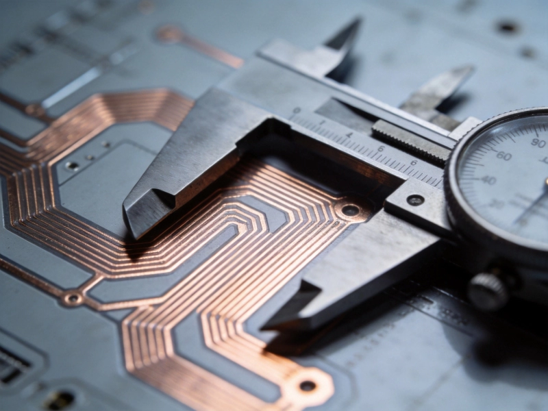
Dimensional verification of critical features becomes more important for high-frequency boards. Trace width variations of 0.001 inches affect impedance measurably at microwave frequencies. CMM inspection of trace geometry complements electrical testing by identifying processing variations.
Not all PCB shops handle high-frequency materials competently. Establishing successful partnerships requires evaluating capabilities and communicating requirements clearly.
Ask potential fabricators about their PTFE experience specifically. Shops that have processed thousands of FR-4 boards may lack PTFE expertise despite general PCB capabilities. Request sample boards demonstrating their high-frequency material processing, and verify performance through electrical testing rather than visual acceptance.
Certification to aerospace or defense quality standards—AS9100, NADCAP—provides third-party verification of process controls. These certifications cost fabricators substantial effort to obtain and maintain, indicating commitment to demanding applications. Military and commercial aerospace programs often require certified suppliers regardless of other qualifications.
Provide complete material specifications including Rogers part numbers or equivalent. Avoid generic descriptions like "low-loss substrate" that leave material selection to fabricator interpretation. Specify thickness tolerances, dielectric constant requirements, and any critical electrical parameters like dissipation factor maximums.
Design documentation should clearly indicate Controlled Impedance requirements, test methods, and acceptance criteria. Reference specific IPC or MIL specifications for high-frequency applications—IPC-2141 for controlled impedance and IPC-4103 for high-frequency materials provide industry-standard frameworks for requirements communication.
High-frequency PCB Fabrication with Rogers and PTFE materials demands attention to material properties, manufacturing processes, and testing requirements exceeding standard PCB practices. Understanding why specialized materials outperform FR-4 at RF frequencies enables informed material selection matching application requirements to material capabilities.
Material selection requires balancing electrical performance, environmental robustness, Thermal Management, and cost considerations. The lowest-loss material isn't always optimal—application requirements determine appropriate specifications. RO4000 series materials serve many commercial applications adequately at reasonable cost while premium PTFE materials justify their premiums for demanding aerospace and Defense Systems.
Fabrication partner selection matters as much as material choice. Shops experienced with high-frequency materials deliver consistent results while general-purpose fabricators may struggle with PTFE-specific processing requirements. Invest time in vendor qualification to avoid production surprises.
Assembly processes require adaptation for PTFE substrates. Soldering profiles, rework procedures, and handling practices differ from standard boards. Work with assembly partners experienced in high-frequency material assembly or invest in process development before production commitment.
Testing high-frequency boards requires electrical verification beyond standard inspection. Specify impedance testing and loss characterization appropriate to your application requirements. Prototype Testing under actual operating conditions validates designs before production scaling.
The gap between design simulation and fabricated performance narrows with experience and careful process control. Learn from early prototypes, iterate designs based on measurements, and build institutional knowledge around your specific material and process choices. High-frequency Pcb success comes from matching design intent to fabrication reality through systematic engineering discipline.
Environmental Considerations in Sustainable High Frequency PCB FabricationSeptember/23/2026
Laser Drilling and Microvias in Modern High Frequency PCB FabricationJuly/07/2026
The Impact of Surface Roughness on High Frequency PCB Fabrication QualityJune/27/2026
High Frequency PCB Fabrication: Managing Dielectric Constant (Dk) TolerancesJune/09/2026
High Frequency PCB Fabrication Tolerances: Why Precision Matters More Than EverSeptember/02/2026
Advanced High Frequency PCB Fabrication Techniques for Low Loss PerformanceMay/29/2026
The Role of Vacuum Lamination in High Frequency PCB FabricationAugust/07/2026
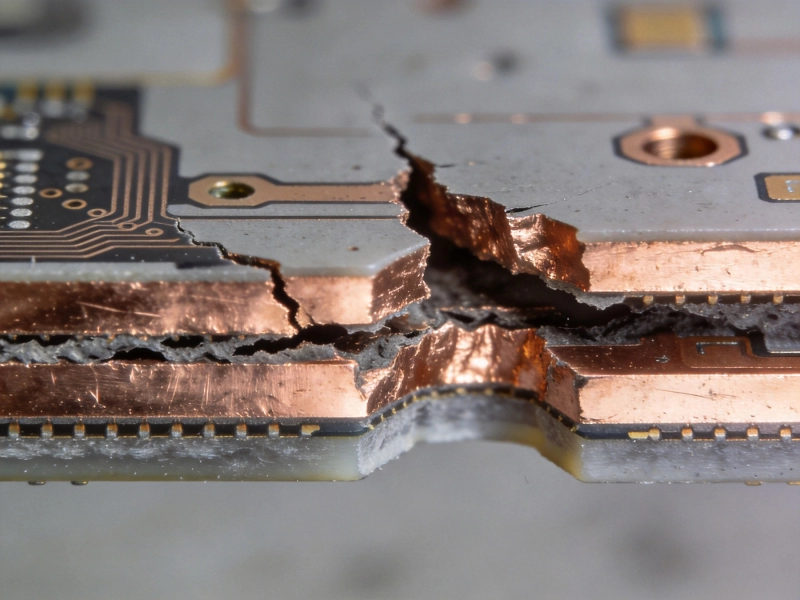
Overcoming Delamination Challenges in Multilayer High Frequency PCB FabricationJuly/28/2026