Open Nav

When signals operate at frequencies measured in gigahertz, the choice of PCB material becomes as critical as the circuit design itself. At low frequencies, standard Fr-4 fiberglass works adequately. But above 1 GHz, the electrical properties of your substrate start dictating performance. Signal Loss, impedance consistency, and frequency response all depend on what your board is made of.
High Frequency Pcb Materials have evolved specifically to address the electrical demands of RF and microwave applications. These specialized substrates offer controlled dielectric constants, minimal Signal Loss, and stable performance across frequency and temperature ranges. Understanding the differences between material families—PTFE, ceramic-filled, and hydrocarbon—helps engineers make informed decisions that directly impact end-product performance.
This guide covers the fundamentals of High Frequency Pcb Materials, comparing the major material families, explaining key properties, and providing practical guidance for material selection in different applications.
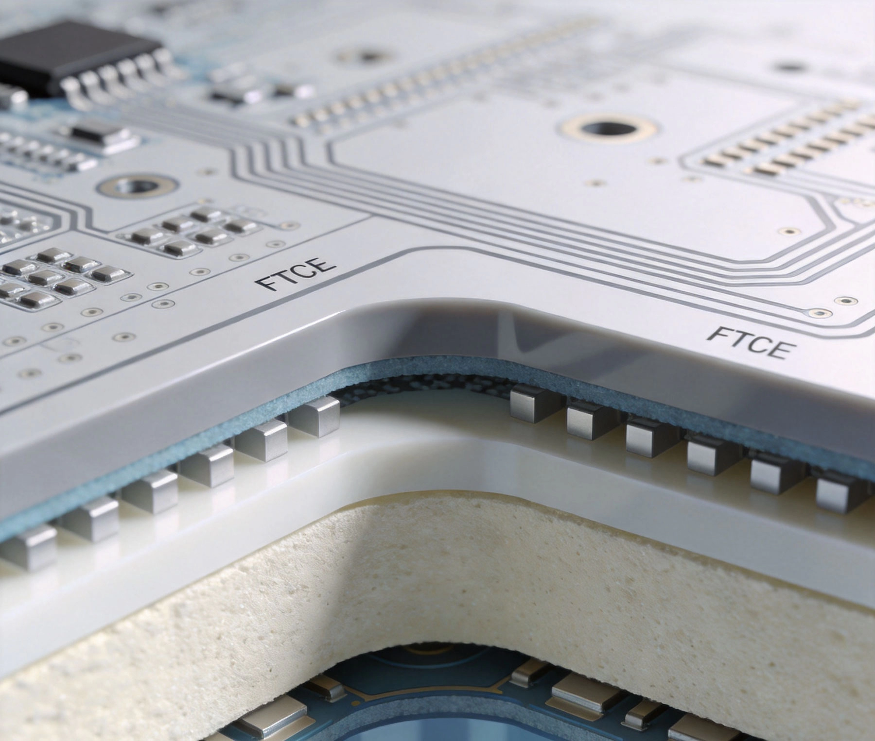
At low frequencies, PCB substrate acts primarily as a mechanical support structure. Electrical signals travel through conductors with minimal interaction with the surrounding material. This changes dramatically as frequency increases.
The Dielectric Constant (Dk or εr) of your substrate directly affects signal propagation velocity. Signals travel more slowly through higher-Dk materials. At microwave frequencies, this slowdown becomes significant enough to affect circuit behavior.
For transmission lines, the effective Dielectric Constant determines Characteristic Impedance and wavelength. Consistent Dk across the board ensures predictable performance. Variations in Dk—caused by material inconsistencies or temperature changes—create impedance mismatches that degrade signal quality.
The loss tangent (Df or tan δ) measures how much energy the substrate dissipates as heat during each signal oscillation. Lower loss tangent means less signal attenuation. At high frequencies, even small loss tangents compound into substantial total loss over circuit paths.
Fr-4 materials typically have loss tangents around 0.02 at 1 GHz. This is acceptable for digital logic but disastrous for RF applications where signals might travel meters of Transmission Line. High Frequency Materials achieve loss tangents of 0.002 or lower—ten times better.
Rf Circuits often operate across wide temperature ranges. Material properties that drift with temperature cause circuit performance to vary with thermal conditions. High Frequency Materials offer better thermal stability, maintaining consistent electrical properties from -40°C to +125°C or beyond.
Polytetrafluoroethylene—commonly known by the brand name Teflon—represents the gold standard for ultra-high frequency applications. PTFE's molecular structure gives it exceptional electrical properties that no other material family matches.
PTFE offers outstanding electrical characteristics:
These properties make PTFE the material of choice for applications where Signal Integrity cannot be compromised.
PTFE's exceptional properties come with practical challenges:
Commercial PTFE Pcb Materials use reinforcements to address mechanical weaknesses:
Woven Glass Reinforcement
Ceramic-Filled PTFE
PTFE materials excel in applications demanding minimal signal loss:
Ceramic-filled laminate materials offer a middle ground between PTFE performance and conventional FR-4 processability. These materials have become the workhorse for commercial RF and microwave applications.
Ceramic particles—typically aluminum oxide, alumina, or titanium dioxide—are combined with organic resins to create composites with controlled electrical properties:
Ceramic-filled materials offer practical advantages:
Ceramic-filled materials process much like standard Pcb Materials:
Ceramic-filled materials serve commercial RF applications well:
Hydrocarbon-based laminates represent an evolution beyond traditional FR-4, offering significantly improved high-frequency performance while maintaining good processability. These materials have become widely adopted in commercial wireless applications.
Hydrocarbon laminates use hydrocarbon resin systems reinforced with woven glass or other fibers. The hydrocarbon chemistry provides better electrical properties than epoxy while remaining processable with conventional equipment:
Hydrocarbon materials offer balanced performance:
Hydrocarbon materials enable useful hybrid constructions:
Each material family offers a different balance of performance, processability, and cost. Understanding these trade-offs helps guide material selection.
| Property | PTFE | Ceramic-Filled | Hydrocarbon |
|---|---|---|---|
| Typical Dk Range | 2.1 - 3.0 | 3.0 - 10.2 | 2.55 - 3.6 |
| Loss Tangent at 10 GHz | 0.0004 - 0.002 | 0.002 - 0.004 | 0.0025 - 0.0035 |
| Thermal Stability | Excellent | Very Good | Good |
| Moisture Resistance | Excellent | Very Good | Good |
| Processability | Challenging | Moderate | Good |
| Relative Cost | Highest | Moderate-High | Moderate |
Select PTFE-based materials when:
Select ceramic-filled materials when:
Select hydrocarbon materials when:
Material selection influences circuit design approaches. Different substrates require different design techniques.
All high-frequency designs require Controlled Impedance transmission lines. Material Dk determines the physical dimensions needed:
Vias introduce discontinuities at high frequencies. Material selection affects via design:
High-frequency performance benefits from good grounding practices:
Material selection affects component matching:
Material choice directly impacts manufacturing approach and cost.
PTFE requires specialized processing:
Ceramic-filled materials process more conventionally:
Regardless of material, following Dfm principles helps:
High-frequency materials cost more than FR-4, but the premium varies significantly by material family.
Different applications have different priorities. Use this guide to match materials to requirements.
Requirements: Ultra-low loss, excellent consistency, automotive-grade reliability
Recommended: High-quality ceramic-filled PTFE or pure PTFE composites
Requirements: Low loss, good thermal management, cost-effective at volume
Recommended: High-quality ceramic-filled PTFE or hydrocarbon composites
Requirements: Good loss performance, volume cost effectiveness, proven reliability
Recommended: Ceramic-filled hydrocarbon or hydrocarbon composites
Requirements: Moderate performance, cost-sensitive, high volume
Recommended: Hydrocarbon materials or high-quality ceramic-filled
Requirements: Maximum performance, extended temperature range, proven reliability
Recommended: High-quality PTFE materials with full qualification
High frequency Pcb Material Selection directly impacts RF and microwave circuit performance. The choice between PTFE, ceramic-filled, and hydrocarbon materials involves balancing electrical performance, manufacturing complexity, and cost for your specific application requirements.
PTFE materials offer the best electrical performance but require specialized manufacturing and carry significant cost premiums. Reserve PTFE for applications where signal loss cannot be tolerated—automotive radar, aerospace, and defense applications at frequencies above 20 GHz.
Ceramic-filled materials provide excellent performance with reasonable processability, making them the workhorse for commercial RF applications from 1 GHz to 30 GHz. The wider Dk range also enables compact designs where board space matters.
Hydrocarbon materials offer the best balance of performance, processability, and cost for applications below 10 GHz. Their compatibility with standard Pcb Manufacturing makes them attractive for high-volume commercial applications.
Successful high-frequency PCB development requires close collaboration between designers, material suppliers, and fabricators. Understanding the trade-offs between material families helps guide discussions and ensures that material selection aligns with application requirements, manufacturing capabilities, and budget constraints.
The best material depends on your specific requirements. For ultra-high frequencies (above 20 GHz) where loss cannot be tolerated, PTFE-based materials offer the lowest loss. For commercial RF applications between 1 GHz and 20 GHz, ceramic-filled materials provide the best balance of performance and cost. For lower frequencies or high-volume applications, hydrocarbon materials often represent the most cost-effective choice.
FR-4 works for some RF applications, typically below 1 GHz or for low-loss-requirement circuits. However, FR-4's higher loss tangent causes significant signal attenuation at higher frequencies, and its higher Dk tolerance can make Impedance Control difficult. For professional RF applications, high-frequency materials are strongly recommended.
Dielectric constant tolerance indicates how much the material's Dk can vary from the nominal value. Tighter tolerances—typically ±0.05 or better—enable more consistent Impedance Control across the board and between boards. Wider tolerances make it harder to achieve precise Impedance Matching at high frequencies.
High-frequency materials exhibit Dk variation with temperature, characterized by the thermal coefficient of dielectric constant (TCDk). Lower TCDk values indicate more stable performance across temperature ranges. PTFE and ceramic-filled materials generally offer better thermal stability than hydrocarbon or FR-4 materials.
Standard high-frequency materials typically have lead times of 2-4 weeks, similar to conventional materials. Specialty materials or unusual thicknesses may require 4-8 weeks. PTFE materials often have longer lead times due to limited domestic stock and specialized processing requirements.
Understanding Thermal Stability in High Frequency PCB MaterialsAugust/10/2026
Rogers vs. FR4: Choosing the Right High Frequency PCB MaterialsJune/12/2026
Top 5 High Frequency PCB Materials for 5G Base Station ApplicationsJuly/30/2026
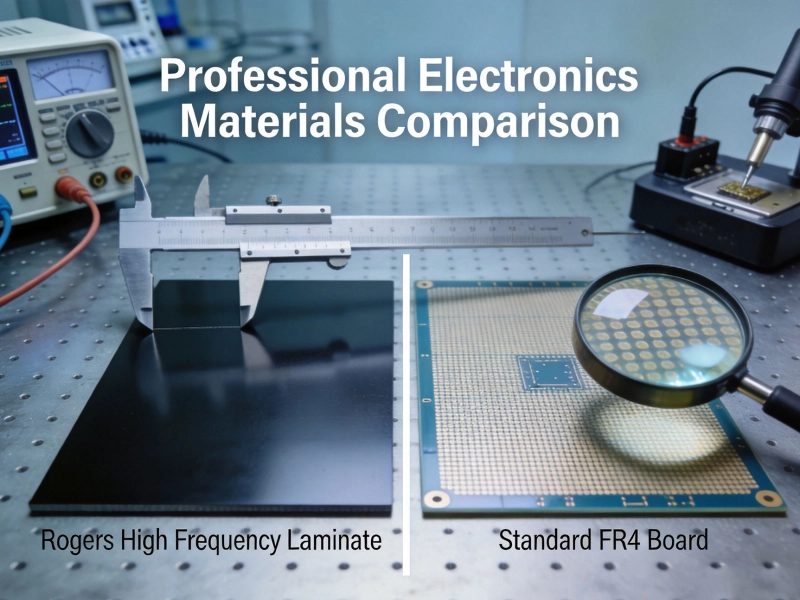
Choosing the Right High Frequency PCB MaterialsMay/29/2026
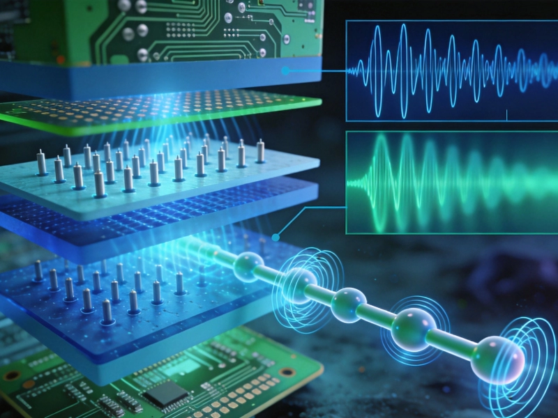
How Dielectric Constant (Dk) and Loss Factor (Df) Affect High Frequency PCB MaterialsJuly/18/2026
High Frequency PCB Knowledge: Managing Crosstalk and EMI in Dense LayoutsAugust/11/2026
High Frequency PCB Capabilities for Aerospace and Defense ApplicationsJuly/17/2026
How High Frequency PCB Applications are Powering the AI Server RevolutionAugust/03/2026