Open Nav
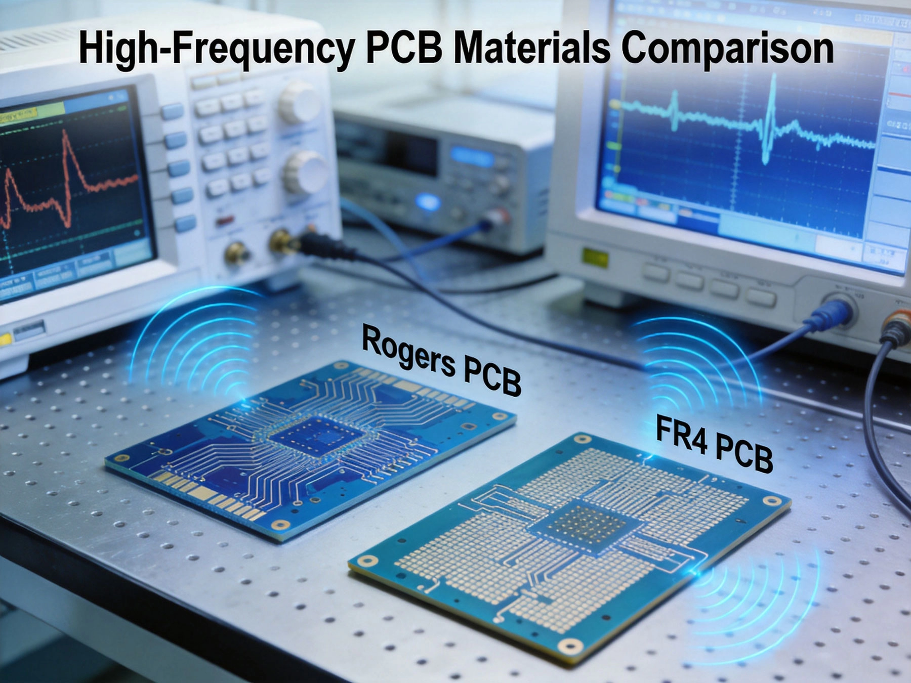
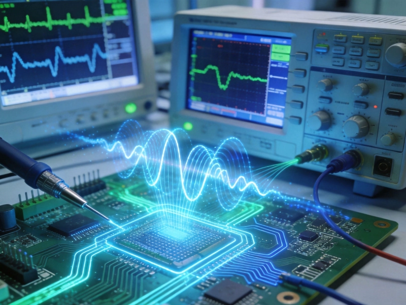
The printed circuit board sits at the heart of every electronic system, serving as the foundation upon which Signal Integrity either thrives or collapses. When your designs operate in the radio frequency (RF) and microwave spectrum—above 1 GHz—substrate selection becomes a critical decision that directly impacts performance, reliability, and ultimately, project success. Among the available options, the choice between Rogers materials and standard FR4 represents one of the most consequential decisions facing RF and microwave engineers today.
This comprehensive guide examines the fundamental differences between Rogers and FR4 Pcb Materials, providing the technical foundation and practical decision framework you need to select the optimal substrate for your specific application. Whether you're designing 5G communication infrastructure, Automotive Radar systems, or high-speed digital interconnects, understanding these material differences empowers you to make choices that balance performance requirements against practical constraints.
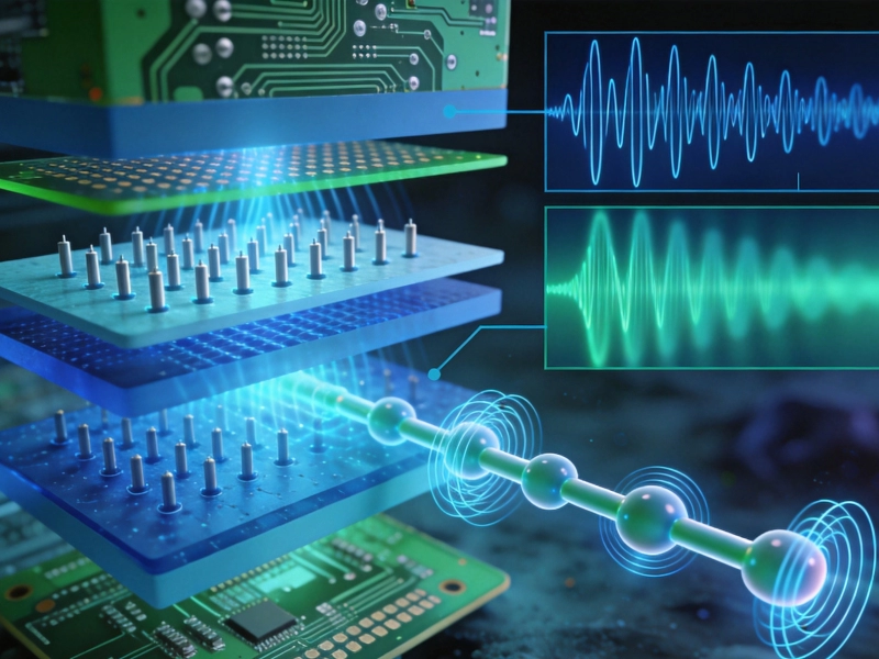
Before diving into specific material comparisons, it's essential to understand what substrate materials actually do in your circuits. The PCB substrate isn't merely mechanical support—it actively participates in signal transmission through its dielectric properties, influencing how electromagnetic waves propagate through your transmission lines.
The substrate material determines your circuit's Characteristic Impedance, affects signal propagation velocity, contributes to Insertion Loss, and influences how signals behave across temperature ranges and frequency spectrums. In low-frequency digital designs, these effects are subtle enough to ignore. At RF and microwave frequencies, however, substrate properties become dominant factors that engineers must carefully control.
Several material properties determine how well a substrate performs in high-frequency applications:
Dielectric Constant (Dk or εr): This fundamental property measures how the material affects the electric field within it. A lower Dk allows faster signal propagation and makes Impedance Control easier. More critically, Dk must remain stable across your operating frequency range—variations cause signal dispersion and phase distortion.
Dissipation Factor (Df or tanδ): This measures energy loss within the dielectric material when exposed to alternating electric fields. Lower Df means less signal attenuation due to heat loss within the substrate. At high frequencies, even small differences in Df translate to substantial Insertion Loss differences over practical transmission line lengths.
Thermal Coefficient of Dielectric Constant (TCDk): This indicates how much the dielectric constant changes with temperature. Lower values mean more stable performance across environmental temperature ranges—a critical factor for automotive, aerospace, and outdoor applications.
Moisture Absorption: Materials that absorb moisture experience dielectric property changes as water molecules infiltrate the substrate. Since water has a high Dk of approximately 80, even small moisture absorption can significantly alter circuit behavior.
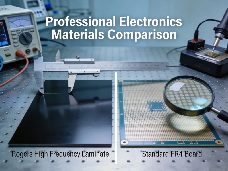
FR4 (Flame Retardant 4) dominates the PCB industry by volume, comprising the vast majority of circuit boards manufactured globally. This glass-reinforced epoxy laminate offers several compelling advantages that explain its ubiquity.
FR4 consists of woven glass fabric reinforcement bonded with epoxy resin. The glass provides mechanical strength and dimensional stability, while the epoxy delivers electrical insulation and facilitates lamination processing. The material earned its "flame retardant" designation from meeting UL94 V-0 burn resistance standards—a requirement for most commercial electronics.
At 1 MHz, standard FR4 exhibits a dielectric constant between 4.2 and 4.8, though this value varies by resin content and glass weave style. The Dissipation Factor typically ranges from 0.015 to 0.025 at 1 MHz, appearing modest on datasheets. However, both Dk and Df exhibit significant frequency dependence, and at 10 GHz, FR4's effective Dk may have decreased while Df increases substantially.
Perhaps more concerning for production consistency, FR4 dielectric properties vary between batches due to manufacturing tolerances in resin content, glass weave density, and cure parameters. Dk tolerances of ±0.2 or wider are common, making precise Impedance Control challenging across different board lots.
For applications below 1 GHz, particularly with modest transmission line lengths, FR4 remains an excellent choice. Consumer electronics, digital control circuits, power supplies, and most industrial control applications operate successfully on FR4. The material's combination of low cost, excellent processability, and adequate performance for lower frequencies makes it the default substrate for most PCB applications.
Even in some RF applications, FR4 finds appropriate use. Bluetooth modules operating at 2.4 GHz with very short trace lengths may perform adequately on FR4, particularly for cost-sensitive consumer products where ultimate performance isn't critical.
Rogers Corporation developed their high-frequency laminate materials specifically to address the limitations of conventional substrates in RF and microwave applications. These purpose-engineered materials offer dramatically improved electrical performance, but at significantly higher cost and with some processing complexities.
Rogers produces several material families optimized for different application requirements:
RO4000 Series: Ceramic-filled hydrocarbon thermosets offer the best balance of high-frequency performance and processing compatibility with standard FR4 manufacturing equipment. RO4350B (Dk = 3.48, Df = 0.0037) has become one of the most widely used RF substrate materials globally. RO4003C (Dk = 3.38, Df = 0.0027) targets applications requiring slightly lower Dk.
RO3000 Series: PTFE-based materials deliver superior high-frequency performance with extremely low loss. RO3003 (Dk = 3.00) and RO3006 (Dk = 6.15) serve demanding microwave applications. These materials require specialized processing compared to standard boards.
RT/duroid Series: Ultra-low loss PTFE composites designed for aerospace, defense, and the most demanding microwave applications. RT/duroid 5880 (Dk = 2.20, Df = 0.0009) represents the pinnacle of low-loss performance for frequencies up to and beyond 77 GHz.
The dielectric properties of Rogers materials remain remarkably stable across frequency and temperature ranges that would cause FR4 performance to degrade significantly. RO4350B maintains Dk variation below ±0.05 across 1-40 GHz, with Df staying below 0.004 throughout this range.
This stability translates directly to practical benefits: more predictable impedance control, consistent phase behavior across bandwidth, and reliable performance across operating temperature ranges. For designs where these factors matter—virtually any serious RF application—Rogers materials provide a margin of performance assurance that FR4 simply cannot match.
Understanding the practical implications of material differences requires examining specific performance metrics side by side.
Insertion loss represents one of the most significant performance differentiators. At 10 GHz, a 50-ohm microstrip line on FR4 typically exhibits insertion loss around 0.5-0.8 dB per inch, while the same line on RO4350B loses only approximately 0.2-0.25 dB per inch. For a 4-inch RF transmission line, this difference—roughly 2.5 dB total loss on FR4 versus 0.8 dB on Rogers—can be the difference between a functional link budget and a failed one.
The loss difference becomes even more pronounced at millimeter-wave frequencies above 24 GHz, where FR4 losses become prohibitive for many applications while Rogers materials continue performing adequately.
FR4's dielectric constant varies with frequency, temperature, and even humidity absorption. At 10 GHz, effective Dk may have shifted 5-8% from the 1 GHz value, making it difficult to achieve precise Impedance Matching without extensive testing and calibration for each production lot.
Rogers materials demonstrate Dk variations below 0.5% across similar conditions, enabling reliable impedance control and repeatable production results. For high-volume manufacturing where consistency matters, this stability represents a significant advantage.
A phenomenon unique to glass-reinforced substrates like FR4, the glass weave effect occurs when transmission lines pass over regions with varying glass weave density. Since glass (Dk ≈ 6) has different dielectric properties than epoxy (Dk ≈ 3), the periodic pattern causes local impedance variations that create phase noise and differential mode conversion.
This effect becomes increasingly problematic at higher frequencies where the weave period approaches signal wavelengths. Rogers materials, particularly those using random glass mat or non-woven glass reinforcement, eliminate this source of performance variation.
FR4's dielectric constant changes significantly with temperature—typically 100-200 ppm/°C for Dk. In automotive applications operating from -40°C to +125°C, this translates to impedance variations of 5-10% that may exceed design margins.
Rogers materials exhibit TCDk values of approximately 40 ppm/°C or lower, maintaining impedance within tighter tolerances across wide temperature ranges. This thermal stability proves essential for Automotive Radar, outdoor wireless infrastructure, and aerospace applications.
Material costs represent the most significant practical barrier to Rogers adoption. Rogers RO4350B typically costs 8-15 times more per square foot than standard FR4, with specialized materials like RT/duroid potentially reaching 30 times the price or higher.
This cost premium reflects both the specialized manufacturing processes required and the relatively lower production volumes compared to commodity FR4. For high-volume consumer products, the cost difference can substantially impact product economics even when Rogers would deliver better performance.
Several application categories consistently justify Rogers material selection:
Modern vehicles increasingly rely on radar systems operating at 24 GHz and 77 GHz for advanced driver assistance features. These frequencies, combined with the demanding thermal environment of automotive operation (-40°C to +125°C+), make Rogers materials essential for reliable performance.
The combination of low loss at millimeter-wave frequencies and stable temperature characteristics enables the consistent beamforming and detection performance that automotive safety systems require. FR4 simply cannot deliver the performance these systems demand.
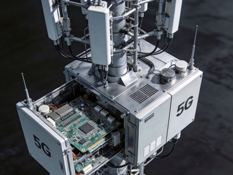
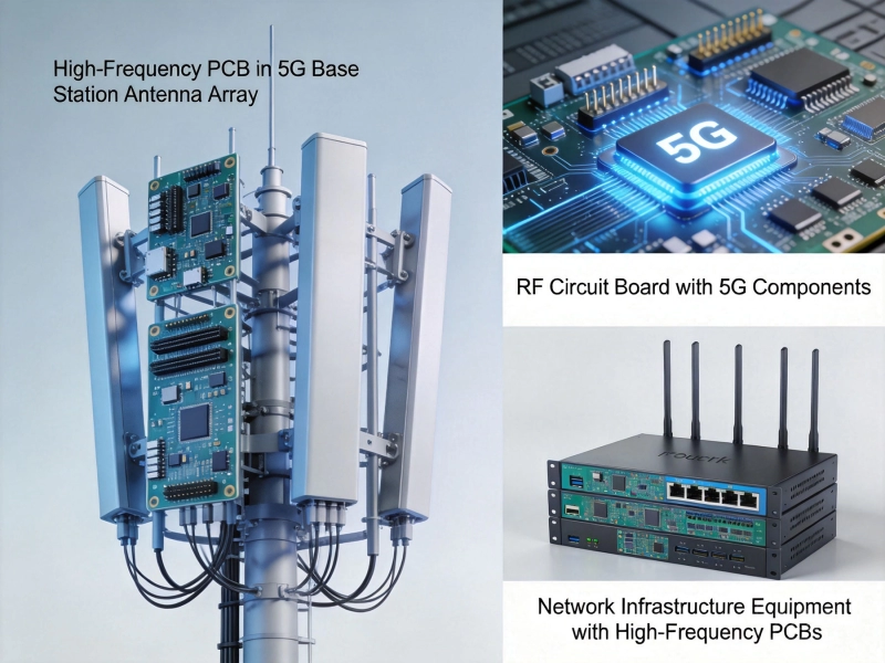
5G networks employ frequencies from sub-6 GHz up to millimeter-wave spectrum above 24 GHz. Base station antenna elements, power amplifiers, and RF front-end modules all benefit from Rogers materials' low loss and stable electrical characteristics.
The high volume of 5G infrastructure deployment makes material costs significant, but the performance requirements leave little room for the compromises FR4 would impose. Rogers RO4350B has emerged as a preferred substrate for 5G applications, balancing performance with manufacturing practicality.
Ka-band and Ku-band Satellite Communications, operating from 12 GHz to 40 GHz, require the lowest possible Signal Loss and exceptional phase stability. Space and aerospace applications also demand materials that maintain performance across extreme temperature ranges and radiation environments.
Rogers RT/duroid and RO3000 series materials serve these demanding applications, providing the performance margins that mission-critical communication systems require.
Any RF receiver chain benefits from minimizing loss before the low-noise amplifier, since each dB of loss before this critical stage directly degrades system noise figure. At frequencies above 5 GHz, Rogers substrates provide the low-loss interconnect that enables receivers to achieve their theoretical noise performance.
Applications including radar receivers, satellite ground stations, and wireless infrastructure base stations consistently specify Rogers materials to preserve the sensitivity that receiver performance demands.
Phased arrays achieving beam steering through precise phase control require material properties that remain consistent across each element in the array. Dk variations between array elements cause beam pointing errors that degrade system performance.
The tight Dk tolerances of Rogers materials, typically ±0.05 compared to FR4's ±0.2 or wider, enable the phase一致性 that large-scale phased arrays require.
Despite Rogers' superior high-frequency performance, FR4 maintains validity in numerous applications:
The vast majority of PCB applications involve digital logic, power management, and control functions that never approach the frequencies where Rogers benefits become significant. Microcontrollers, memory interfaces, power converters, and sensor conditioning circuits all operate effectively on FR4.
Even in systems that include RF sections, the digital portions typically reside on FR4 portions of the board, reserving Rogers for the critical RF interconnects only.
High-volume consumer electronics must meet aggressive cost targets that Rogers' premium pricing cannot justify. Smart watches, fitness trackers, and IoT devices may include wireless connectivity, but their short transmission paths and relaxed performance requirements allow FR4 to deliver adequate results at acceptable cost.
Early-stage development benefits from the speed and economy of FR4 prototyping. Functional verification can proceed on low-cost substrates, reserving Rogers for the final production design where its benefits justify the investment.
Sub-1 GHz RF applications including RFID, legacy cellular bands, and various industrial, scientific, and medical (ISM) frequencies often perform adequately on FR4, particularly when transmission line lengths remain short.
Many practical designs combine FR4 and Rogers materials in hybrid multilayer configurations, capturing benefits of both materials:
In hybrid stackups, Rogers material forms the critical RF layers while FR4 provides mechanical support, cost reduction, and accommodation of through-hole components. This approach is particularly common in modules combining RF front-ends with digital processing, where the expensive RF substrate covers only the necessary area.
Manufacturing hybrid boards requires careful attention to thermal coefficient matching between materials and specialized lamination procedures. Not all PCB fabricators possess the expertise and equipment to produce reliable hybrid boards—select your manufacturing partner carefully for these designs.
Material selection ultimately requires balancing technical requirements against practical constraints:
Evaluate your frequency: Above 3-5 GHz with meaningful trace lengths, Rogers benefits become substantial. Below this threshold, FR4 usually suffices.
Assess your loss budget: Calculate allowable insertion loss and determine whether FR4's higher loss would exceed your margins.
Consider thermal environment: Wide temperature ranges favor Rogers' stable temperature coefficient.
Factor volume and cost: Higher volumes make Rogers' premium more significant; lower volumes reduce its impact.
Verify manufacturing capability: Ensure your chosen fabricator can reliably produce your selected material and stackup.
The Rogers versus FR4 decision isn't about identifying a universally superior material—it's about matching material characteristics to application requirements. Rogers materials deliver dramatically better high-frequency performance, but this performance comes at substantial cost premium and with some manufacturing complexity.
For RF and microwave applications operating above 5 GHz, particularly in demanding thermal environments or where Signal Integrity is critical, Rogers materials represent the engineering choice that best serves performance requirements. For lower frequencies, cost-sensitive applications, or where performance margins allow, FR4 continues delivering excellent value.
The most skilled engineers develop intuition for these tradeoffs, making material selection decisions almost automatically. With the framework provided in this guide, you're now equipped to approach these decisions systematically, balancing technical performance against practical considerations to select the optimal substrate for each unique project requirement.
How Dielectric Constant (Dk) and Loss Factor (Df) Affect High Frequency PCB MaterialsJuly/18/2026
Choosing the Right High Frequency PCB MaterialsMay/29/2026
The Ultimate Guide to High Frequency PCB Materials: PTFE, Ceramic, and HydrocarbonJuly/08/2026
Ensuring Signal Integrity During High Frequency PCB Assembly ProcessesJuly/15/2026
Common Pitfalls to Avoid During Your High Frequency PCB Prototype PhaseJune/18/2026
Top High Frequency PCB Applications in the 5G and Telecommunications IndustryMay/29/2026
Understanding High Frequency PCB Capabilities: Line Width, Spacing, and Layer CountJune/28/2026
Top High Frequency PCB Applications in the 5G and Telecommunications IndustryJune/16/2026