Open Nav

Every PCB substrate material influences how electrical signals propagate through copper traces, but at high frequencies this influence becomes the dominant factor determining whether a design succeeds or fails. The Dielectric Constant (Dk) and dissipation factor (Df) of Pcb Materials directly control signal velocity, impedance, and power loss in ways that low-frequency designers can safely ignore. Engineers working with Rf Circuits, microwave systems, and high-speed digital designs must understand these material properties to select substrates that enable reliable performance.
This article explains how Dielectric Constant and dissipation factor affect PCB electrical behavior, compares common material families, and provides practical guidance for matching materials to application requirements. Understanding these fundamental material properties separates successful high-frequency designs from frustrating field failures.
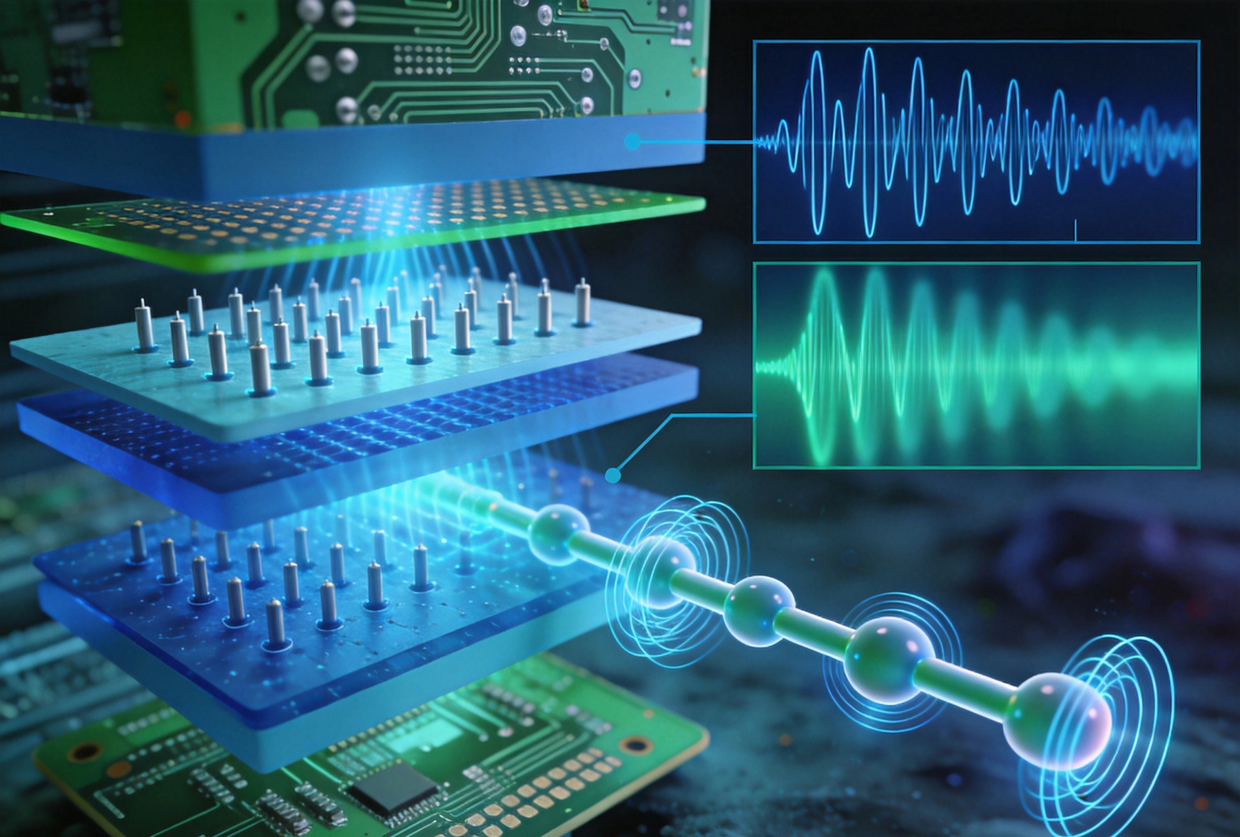
Dielectric constant, also called relative permittivity and denoted as Dk or εr, quantifies how much a material reduces the strength of an electric field compared to vacuum. Vacuum serves as the reference with Dk equal to 1.0. All Pcb Substrate Materials have Dk values greater than 1, ranging from approximately 2.5 for low-loss hydrocarbon ceramics to over 10 for certain ceramic-filled composites.
When a voltage difference exists between two conductors separated by dielectric material, the electric field between them passes through the material. The dielectric constant determines the capacitance that results from this field configuration. Higher Dk materials produce higher capacitance for the same geometry, while lower Dk materials reduce capacitance.
Signal velocity in a Transmission Line depends on the dielectric constant of the surrounding material. Higher Dk materials slow signal propagation according to the relationship velocity = c / √Dk, where c is the speed of light in vacuum. This slowdown directly affects propagation delay, which matters for timing-sensitive designs where signal arrival times must be predictable.
Characteristic Impedance of a Transmission Line also depends on dielectric constant. For Microstrip traces, impedance varies inversely with the square root of Dk. This means that substrate Dk directly affects the trace dimensions needed to achieve target impedance. Variations in Dk across a panel or between production lots shift impedance values from design targets, requiring tighter process control for consistent performance.
Dielectric constant is not constant across all conditions. Temperature fluctuations change Dk for most materials, with temperature coefficient of dielectric constant (TCDk) quantifying this sensitivity. Designs operating across wide temperature ranges must account for Dk variation that affects impedance and propagation delay.
Manufacturing tolerances on Dk typically range from ±5% for standard materials to ±2% for premium controlled-constant laminates. High-frequency designs requiring tight Impedance Control may need to specify low-Dk tolerance materials or implement impedance tuning features that compensate for Dk variations. Some fabricators measure and certify Dk values for critical production lots.
Dissipation factor, also called loss tangent or tan δ, quantifies how much electrical energy a dielectric material converts to heat rather than storing and releasing it. When an alternating electric field passes through the material, molecular friction converts some signal energy to thermal loss. Lower Df values indicate better Dielectric Materials with less energy loss.
Df values for Pcb Materials range from 0.001 (0.1%) for ultra-low-loss ceramics to 0.035 (3.5%) for standard Fr-4. At low frequencies, this loss is negligible. At high frequencies, dissipation factor directly determines how much signal attenuation occurs per unit distance, making material Df critical for RF and microwave designs.
Dielectric loss causes signal amplitude to decrease exponentially with distance traveled through lossy material. The attenuation constant in nepers per meter depends on frequency, Df, and Dk according to relationships that show loss increasing proportionally with frequency. A material with Df of 0.01 at 1GHz might be acceptable, but the same material at 10GHz would introduce ten times more loss per unit length.
For long RF Transmission Lines and high-frequency circuits, this loss accumulates significantly. Designers must budget total loss across the signal path, ensuring that received signal amplitude remains sufficient for reliable detection. Material Df selection must account for both the frequencies present in the signal spectrum and the total path length.
Dielectric constant and dissipation factor are independent material properties, but practical materials often show correlations between them. Generally, lower-Dk materials achieve lower Df values more easily than high-Dk ceramics. This means that choosing a material for low loss often results in lower dielectric constant as well, affecting impedance and propagation characteristics.
Material data sheets list both Dk and Df at specific frequencies, typically 1MHz or 10GHz, with notes about how values change across frequency ranges. Some materials exhibit relatively flat Df versus frequency while others show significant variation. For broadband applications, understanding frequency-dependent behavior is essential for accurate performance prediction.
Fr-4 epoxy-glass laminate serves admirably for digital circuits up to several hundred megahertz but becomes problematic at RF frequencies. Its Df of approximately 0.02-0.035 introduces significant loss at microwave frequencies. Additionally, FR-4's Dk varies considerably with glass weave content, creating local impedance variations that degrade signal quality.
The glass reinforcement in FR-4 creates dielectric constant discontinuities wherever glass fibers cluster or disperse. At frequencies above 5GHz, these variations cause measurable phase distortion and impedance deviations. For emerging 5G applications in the GHz range, FR-4 often cannot meet performance requirements despite its cost advantages.
Materials optimized for high-speed digital applications bridge the gap between FR-4 and specialized RF laminates. Products like Rogers Ro4003c, Panasonic Megtron 7, and Isola IGET ranger provide Df values around 0.002-0.004 while maintaining Dk near 3.5-4.0. These materials support digital interfaces up to 25Gbps with manageable loss budgets.
The fire-retardant ratings and UL certifications of these materials vary. Some high-speed materials lack FR-4 equivalence for flame resistance, requiring additional design consideration for applications with safety requirements. Material suppliers provide comprehensive data sheets that specify all relevant properties for design use.
Purpose-built RF laminates offer the lowest loss and most stable dielectric properties for microwave applications. Ptfe (Teflon) based materials achieve Df values below 0.002 with excellent frequency stability. Ceramic-filled Ptfe composites provide Dk values ranging from 2.1 to 10.2, enabling Impedance Matching and miniaturization trade-offs.
Popular Rf Materials include Rogers RT/duroid series with Dk values from 2.1 to 10.35, and Taconic RF laminates with various Dk and filler options. These materials cost significantly more than FR-4, sometimes five to ten times the price, but enable performance impossible with standard materials. The cost premium is justified when RF performance requirements demand it.
Controlling trace impedance at high frequencies requires accounting for Dk variations in ways that low-frequency design ignores. The effective dielectric constant experienced by Microstrip traces differs from the bulk material Dk because field distribution between the trace, substrate, and air affects the effective permittivity. This effective Dk must be used in impedance calculations.
CAD simulation tools incorporate material Dk into transmission line models, but accurate results depend on correct Dk input. Design teams must verify that material libraries in simulation tools contain appropriate values for the actual substrates being used. Some designers add margin to impedance targets to account for Dk tolerance variations.
High-speed digital designs requiring matched trace lengths must account for the reduced signal velocity in high-Dk materials. Two traces of equal physical length have different electrical lengths if they experience different effective Dk values. For DDR memory interfaces and similar bus architectures, velocity differences affect setup and hold margins.
Differential pair routing requires matched propagation velocity for both conductors to maintain differential Signal Integrity. Any asymmetry in effective Dk between the positive and negative traces converts some differential signal to common-mode, potentially causing Emi emissions and receiver noise rejection problems. Tight coupling between differential pair traces ensures both conductors experience similar dielectric environments.
Dielectric loss converts signal power to heat within the substrate material. While individual Transmission Lines dissipate modest power, densely packed high-frequency boards may generate significant total thermal loading. The dissipated power density depends on signal frequency, amplitude, and the substrate Df value.
Power amplifier output stages experience the most severe dielectric heating. The combination of high signal power and lossy substrate can raise board temperatures enough to affect reliability. Low-Df materials are essential for these applications, and thermal via patterns may be required to transfer heat away from critical areas.
Accurate Dk and Df measurement employs specialized techniques including resonant cavity methods, transmission line measurements, and split-post dielectric resonator characterization. Each method has frequency range and accuracy limitations. IPC standard test methods define procedures for measuring dielectric properties at specific frequencies.
Clamped stripline resonator testing provides a practical production measurement method where test traces are measured before and after clamping a dielectric sample. This approach enables material characterization without manufacturing complete boards. For production boards, time-domain reflectometry (Tdr) can measure effective Dk through the signal response of Controlled Impedance traces.
Specifying dielectric properties requires balancing accuracy needs against supplier capabilities and cost. Tight Dk tolerances generally require premium-grade materials with verification testing. The specification should reference appropriate test methods to avoid ambiguity about acceptable values.
Material datasheets typically specify Dk and Df at 10GHz using IPC test methods. Some applications may need characterization at different frequencies. The specification should include frequency of interest if different from the standard measurement frequency. Material certification from suppliers provides traceability that ensures the delivered product meets requirements.
FR-4, the ubiquitous standard, offers Dk of 4.2-4.5 with Df of 0.02-0.035. Cost-effective for digital applications below 1GHz, but loss limits RF performance.
Rogers Ro4003c provides Dk of 3.38 with Df of 0.0027. Popular for Microwave Circuits from 5-20GHz, offering good balance of electrical performance and processability.
Rogers RT/duroid 5880 features Dk of 2.2 with Df of 0.0009. Ultra-low loss PTFE material ideal for frequencies from 10GHz to 77GHz and beyond, commonly used in radar and aerospace applications.
Isola IGET guardian achieves Dk of 3.7 with Df of 0.003. Halogen-free high-speed material designed for digital applications up to 25Gbps, offering good processability similar to FR-4.
Panasonic Megtron 7 provides Dk of 3.5 with Df of 0.002. Premium digital laminate for high-speed applications including 56Gbps SerDes interfaces.
5G infrastructure operates at frequencies from 600MHz to 39GHz, with massive MIMO antenna systems requiring boards with consistent Dk across large areas. The beamforming algorithms in these systems depend on consistent phase relationships between antenna elements, demanding tight Dk tolerance and low loss. Rogers TC series materials with thermal compensation address these requirements.
Base station power amplifier boards must handle high RF power while maintaining efficiency. Low-Df PTFE materials prevent excessive heating and Signal Loss. The cost premium for premium materials is justified by improved efficiency and reliability in these high-value systems.
Automotive Radar systems operating at 77GHz and 79GHz demand extremely Low-loss Materials for the long transmission lines connecting radar modules. Automotive-qualified versions of PTFE materials meet the reliability requirements for under-hood and body-mount installations. The vibration, temperature, and humidity conditions in vehicles require robust material selection.
Adas processor boards operating at lower frequencies still require good Signal Integrity, typically using high-speed digital materials with good processability for automotive manufacturing environments. The qualification requirements for Automotive Electronics are among the most stringent in any industry.
Network analyzers and spectrum analyzers must measure signals with extreme precision, requiring dielectrically stable materials in signal paths. Calibration standards and test fixtures often use air or sapphire rather than composite dielectrics to avoid material-related uncertainties. Where solid substrates are necessary, ultra-stable materials with minimal temperature coefficients are essential.
High-performance oscilloscope acquisition systems employ specialized materials for RF front ends and signal distribution. The bandwidth requirements for 100GHz+ oscilloscopes push material selection to the limits of available technology. Material innovation continues to enable the measurement capabilities that advance all other electronic development.
Dielectric constant and dissipation factor fundamentally determine how PCB materials behave at high frequencies. Dk controls signal velocity and impedance characteristics, while Df determines power loss and attenuation. Understanding these properties and their implications enables engineers to select materials that meet application requirements without unnecessary cost premium.
Material selection requires balancing electrical performance against cost, processability, and reliability requirements. Standard FR-4 serves many applications adequately, but RF and high-speed digital designs increasingly demand specialized laminates. The gap between FR-4 and Rf Materials contains many options optimized for different combinations of Dk, Df, and cost.
As electronic systems continue pushing toward higher frequencies and data rates, dielectric material performance becomes ever more critical. The materials that enable 5G networks, Automotive Radar, and terabit communications build on decades of dielectric material development. Understanding Dk and Df provides the foundation for selecting and applying these materials effectively.
How to Choose the Right High Frequency PCB Material for RF DesignsOctober/21/2026
The Impact of Copper Foil Type on High Frequency PCB Materials PerformanceSeptember/16/2026
Understanding Thermal Stability in High Frequency PCB MaterialsAugust/10/2026
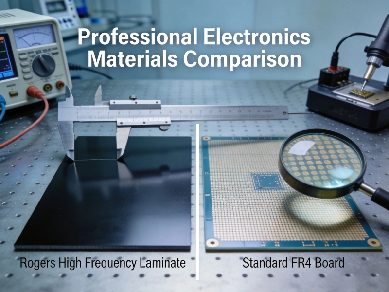
Choosing the Right High Frequency PCB MaterialsMay/29/2026
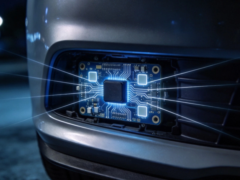
High Frequency PCB Materials for Automotive Radar: Durability and SpeedSeptember/26/2026
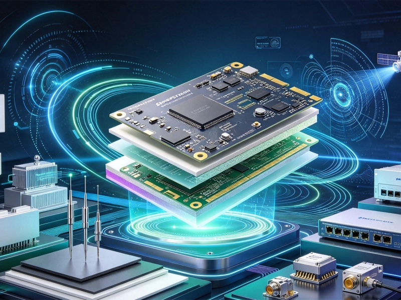
Emerging Trends in High Frequency PCB Materials for Next-Gen CommunicationOctober/10/2026
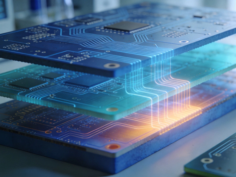
Cost vs. Performance: Selecting Budget-Friendly High Frequency PCB MaterialsSeptember/04/2026

Top 5 High Frequency PCB Materials for 5G Base Station ApplicationsJuly/30/2026