
The automotive industry is undergoing a revolutionary transformation as vehicles evolve from mechanical transportation machines to sophisticated mobile computing platforms. Advanced Driver Assistance Systems (ADAS) and autonomous driving technologies represent the pinnacle of this transformation, requiring unprecedented levels of electronic sophistication to process sensor data, make real-time decisions, and execute control commands with split-second timing. At the heart of these systems lie high frequency printed circuit boards (PCBs) that enable the high-speed data transmission, Signal Integrity, and Electromagnetic Compatibility essential for safe and reliable autonomous operation. These advanced PCB technologies must perform reliably in the challenging automotive environment while meeting stringent quality, reliability, and safety requirements that far exceed those of consumer electronics.
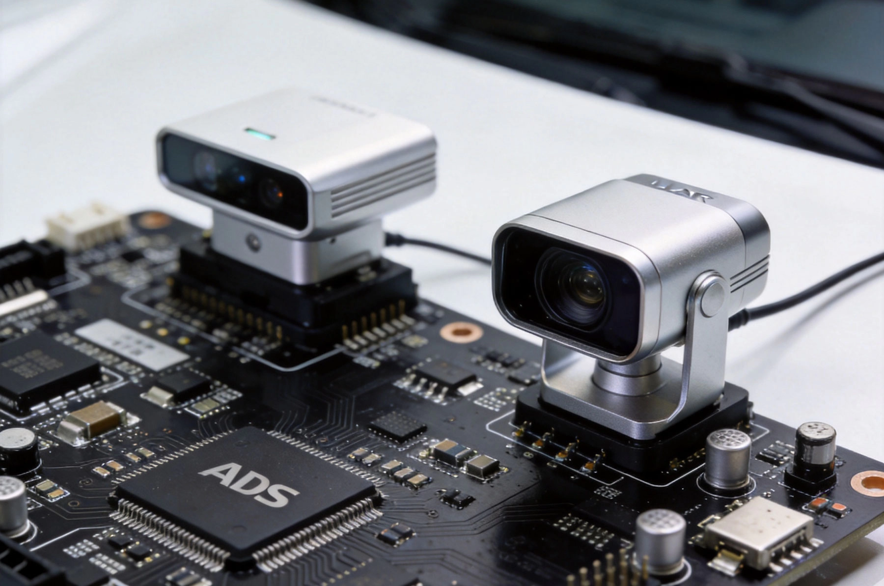
Understanding the role of high frequency PCBs requires context on the ADAS and autonomous driving technologies they support. These systems encompass multiple sensor modalities, processing platforms, and control systems working together to enable vehicle automation.
The Society of Automotive Engineers (SAE) defines six levels of driving automation from Level 0 (no automation) to Level 5 (full automation). Each level requires progressively more sophisticated sensor systems, computing power, and electronic integration:
Level 0-2 (Assisted Driving): These levels include basic driver assistance features including lane keeping assist, adaptive cruise control, and automatic emergency braking. While increasingly sophisticated, the driver remains primarily responsible for vehicle operation.
Level 3 (Conditional Automation): At this level, the vehicle can drive itself under specific conditions such as highway driving, but the driver must remain ready to take control when requested. This represents the first level where the vehicle assumes primary driving responsibility in certain situations.
Level 4 (High Automation): The vehicle can operate autonomously in defined operational design domains (ODDs) without human intervention. These systems may require human takeover only when leaving the ODD or when the system encounters unexpected conditions.
Level 5 (Full Automation): The vehicle can operate autonomously under all conditions without requiring human intervention. This level requires complete sensor coverage, fail-safe systems, and redundancy throughout the vehicle's electronic architecture.
Autonomous vehicles perceive their environment through multiple sensor modalities, each generating high-frequency signals that require sophisticated PCB design for proper transmission and processing:
Cameras: Visual camera systems capture high-resolution imagery at high frame rates. Advanced cameras may operate at 60-120 frames per second with resolutions exceeding 4K, generating massive data bandwidths requiring high-speed interfaces on PCBs.
Lidar: Light Detection and Ranging systems use laser pulses to create detailed 3D maps of the vehicle's environment. High-frequency pulsed laser systems and precise timing circuits require specialized Pcb Materials and designs to maintain Signal Integrity.
Radar: Automotive Radar systems typically operate at 24-77 GHz, requiring Microwave Pcb materials and designs that can handle millimeter-wave frequencies with minimal loss and excellent Electromagnetic Compatibility.
Ultrasonic Sensors: These sensors provide close-range obstacle detection and parking assistance. While operating at lower frequencies than radar, they still require careful signal conditioning and noise rejection on the PCB.
Inertial Measurement Units (IMUs): IMUs provide critical motion data including acceleration and angular velocity. These systems generate high-frequency data streams that must be transmitted with minimal jitter and latency.
Autonomous vehicles incorporate complex computing architectures that process sensor data, make driving decisions, and execute control commands. These architectures include:
Sensor Fusion Units: These systems combine data from multiple sensors using advanced algorithms including Kalman filtering and deep learning. High-speed data buses between sensors and fusion units require high-frequency PCBs capable of maintaining signal integrity across complex interconnects.
Perception Processing: Artificial Intelligence and machine learning algorithms process sensor data to identify objects, detect road features, and understand traffic situations. These algorithms require powerful processors operating at high clock frequencies, demanding PCBs with excellent Power Delivery and Thermal Management capabilities.
Path Planning and Decision Making: Higher-level planning algorithms determine vehicle trajectories and driving decisions. While not as computationally intensive as perception processing, these systems require reliable communication with other vehicle systems.
Control Systems: Vehicle control including steering, braking, and acceleration requires precise real-time performance. Control loops must execute with minimal latency and deterministic timing, influencing PCB design for timing-sensitive signals.
High frequency PCBs for automotive applications face unique challenges that combine high-frequency electrical performance requirements with automotive environmental and reliability standards.
Automotive high-frequency PCBs must handle signals across a broad frequency spectrum:
Radar Frequencies: Automotive Radar operates at 24 GHz for short-range applications and 77 GHz for long-range applications. These millimeter-wave frequencies require specialized Pcb Materials with extremely low dielectric loss and stable dielectric constants.
Camera Interfaces: High-speed camera interfaces including MIPI CSI-2, GMSL, and FPD-Link operate at data rates exceeding 10 Gbps. These interfaces require Controlled Impedance, minimal Signal Loss, and excellent signal integrity across differential pairs.
Lidar Systems: While lidar optical signals don't travel on PCBs, the electronic circuits generating and detecting laser pulses operate at high frequencies requiring careful timing and signal conditioning on the PCB.
Processor Clocks: Modern automotive processors operate at clock frequencies exceeding 2-3 GHz. These high-speed clock signals require careful routing, Controlled Impedance, and Ground Plane design to minimize jitter and Electromagnetic Interference.
High-Speed Memory Interfaces: DDR4/DDR5 memory and other high-speed memory interfaces operate at data rates exceeding 4-5 Gbps, requiring precise Impedance Control and signal integrity management.
Signal integrity is critical for reliable operation of autonomous driving systems. Signal degradation can cause misinterpretation of sensor data, leading to incorrect driving decisions and potentially hazardous situations.
Impedance Control: Controlled impedance Transmission Lines maintain consistent signal characteristics. Differential impedance, single-ended impedance, and Characteristic Impedance must be controlled within tight tolerances typically ±5-10% depending on the specific application.
Signal Loss: Signal attenuation must be minimized to maintain signal-to-noise ratios at receiver inputs. Insertion Loss budgets often limit total PCB trace loss to 0.5-2 dB depending on link length and frequency.
Return Path Integrity: Proper return path design minimizes ground bounce, electromagnetic emissions, and crosstalk. Continuous reference planes under signal traces provide low-impedance return paths and minimize impedance discontinuities.
Termination: Proper termination techniques including series termination, parallel termination, or differential termination prevent signal reflections that could cause data errors or signal integrity problems.
Timing Budget: Strict timing budgets ensure signals arrive within specified timing windows. Timing budgets account for propagation delay, skew, jitter, and setup/hold times. PCB design must minimize variability in these timing parameters.
Electromagnetic compatibility is particularly critical in vehicles where multiple electronic systems operate in close proximity and must not interfere with each other or external systems.
Emissions Control: PCB designs must minimize radiated emissions that could interfere with other vehicle systems or external radio services. Proper Grounding, Shielding, and filtering techniques control emissions.
Immunity: Vehicles operate in electrically noisy environments including ignition noise, motor switching noise, and external RF interference. PCBs must be designed with adequate immunity to these interference sources through proper filtering, Shielding, and layout techniques.
Grounding Strategy: Systematic grounding strategies prevent ground loops, minimize ground bounce, and provide stable reference planes. Star grounding, partitioned ground planes, and careful ground return path design are essential.
Shielding: Conductive enclosures, shielding cans, and ground planes provide electromagnetic shielding for sensitive circuits. Shielding effectiveness depends on material selection, geometry, and implementation details.
Filtering: Power supply filtering, signal line filtering, and I/O filtering prevent noise propagation through PCBs. Component selection and placement critically affect filtering effectiveness.
Automotive electronics must operate reliably across temperature ranges from -40°C to +125°C or higher. Thermal Management becomes especially important for high-frequency circuits that generate significant heat.
Power Dissipation: High-frequency circuits generate substantial heat from both active components and conductive losses in traces and dielectrics. Proper thermal design ensures components operate within specified temperature ranges.
Thermal Conductivity: PCB materials and designs facilitate heat transfer from components to the ambient environment. High thermal conductivity dielectrics, copper planes, and thermal vias improve heat spreading and dissipation.
Thermal Management Integration: PCB thermal design must integrate with vehicle-level thermal management including heat sinks, fans, and airflow. Thermal interface materials, Component Placement, and mechanical design affect overall thermal performance.
Temperature Cycling: Automotive applications experience substantial temperature cycling during operation and environmental changes. PCB designs must accommodate thermal expansion differences between materials without creating mechanical stress failures.
Automotive electronics must meet stringent reliability and quality standards to ensure safe, long-term operation in demanding environments.
AEC-Q100 Qualification: Automotive Electronics Council (AEC) Q100 provides qualification standards for integrated circuits used in automotive applications. PCB materials and designs must support component-level qualification requirements.
IATF 16949: International Automotive Task Force 16949 defines Quality Management System requirements for automotive production. Pcb Manufacturing processes must meet these quality management requirements.
ISO 26262: This functional safety standard for road vehicles defines safety requirements for automotive electrical and electronic systems. PCB designs must support safety-critical system requirements including failure detection and mitigation.
Design Lifetime: Automotive electronics must support vehicle lifetimes of 10-15 years or more. PCB designs must account for long-term aging effects including material degradation, moisture absorption, and thermal cycling fatigue.
Failure Rate Requirements: Automotive systems specify failure rates in FIT (Failures In Time) units, with safety-critical systems requiring extremely low failure rates. PCB design contributes to achieving these reliability targets.
Material selection significantly impacts the performance, reliability, and cost of high-frequency automotive PCBs. Different materials offer varying combinations of electrical, thermal, and mechanical properties.
Dielectric Materials in high-frequency PCBs must meet specific requirements for signal performance and reliability:
Dielectric Constant (Dk): Stable Dielectric Constant across frequency and temperature ensures consistent impedance and signal propagation. Automotive applications require Dk stability within ±2% or better over the operating temperature range.
Dielectric Loss (Df): Low dielectric loss minimizes signal attenuation, especially important at high frequencies. Df values below 0.003 are typical for high-frequency automotive applications, with even lower values required for millimeter-wave radar.
Thermal Expansion Coefficient (CTE): Matching CTE between dielectric and copper reduces stress during thermal cycling. Glass Transition Temperature (Tg) above operating temperatures prevents material softening and degradation.
Moisture Absorption: Low moisture absorption prevents material property changes and potential short circuits in humid environments. Moisture absorption below 0.5% is typically required for automotive applications.
Thermal Conductivity: Higher thermal conductivity improves heat dissipation. Values above 0.5 W/m·K are desirable for high-power applications, though standard Fr-4 typically provides 0.3-0.4 W/m·K.
High-frequency automotive PCBs use several material categories, each with specific advantages and applications:
Polytetrafluoroethylene (Ptfe) Materials: Ptfe-based materials offer the lowest dielectric loss and best high-frequency performance. These materials are essential for millimeter-wave radar applications and other extremely high-frequency circuits. However, they are more expensive and require specialized processing.
Modified Epoxy/Phenolic Materials: These materials balance performance, cost, and manufacturability. Advanced epoxy formulations can achieve Df values of 0.003-0.005, suitable for many automotive high-frequency applications below 10 GHz.
Ceramic-Filled Materials: Ceramic fillers including alumina, silica, or other ceramics improve thermal conductivity and reduce dielectric loss. These materials are particularly useful for Power Electronics and thermal management applications.
Hybrid Materials: Combining different materials in a single board optimizes performance for different sections. For example, PTFE for radar sections and modified epoxy for lower-frequency sections provides performance where needed while controlling cost.
Copper foil properties significantly affect high-frequency performance and signal integrity:
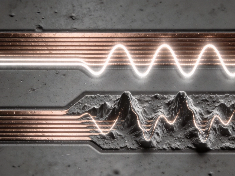
Surface Roughness: Smooth copper foil reduces conductor losses at high frequencies where current concentrates near the surface due to Skin Effect. Reverse-treated foils with surface roughness below 1 μm are preferred for frequencies above 10 GHz.
Foil Thickness: Foil thickness affects both electrical performance and thermal management. Thicker foil reduces resistance and improves thermal conductivity but increases cost and may affect fine-line manufacturability.
Profile: Electrodeposited (ED) and rolled annealed (RA) foils offer different characteristics. RA foils provide smoother surfaces and better fatigue resistance, while ED foils are more common and cost-effective.
Selecting appropriate laminates requires balancing multiple factors:
Frequency Range: Match material properties to operating frequencies. Low-loss Materials are essential for millimeter-wave applications, while standard materials may suffice for lower frequencies.
Cost Constraints: Automotive applications have significant cost pressures. Material selection must balance performance requirements against cost targets, often driving material choices toward the minimum performance needed.
Manufacturing Requirements: Some advanced materials require specialized processing including different drilling parameters, plating processes, or lamination conditions. Material selection must account for manufacturing compatibility.
Regulatory Requirements: Materials must meet automotive environmental and safety regulations including Rohs Compliance, REACH requirements, and flame resistance specifications.
Effective PCB design techniques enable high-frequency signals to perform reliably in automotive environments. These techniques address signal integrity, electromagnetic compatibility, and thermal performance simultaneously.
Controlled impedance routing ensures signals maintain consistent characteristics throughout transmission:
Microstrip vs. Stripline: Microstrip traces (signals on outer layers with Ground Plane underneath) offer easier routing but more exposure to external interference. Stripline traces (signals between ground planes) provide better shielding and electromagnetic compatibility but require more layers.
Impedance Calculation: Accurate impedance calculation accounts for trace width, dielectric thickness, dielectric constant, copper thickness, and nearby conductors. Field solvers provide the most accurate impedance predictions for complex geometries.
Impedance Matching: Source, Transmission Line, and load impedances must be matched to prevent reflections. Mismatches cause signal reflections, standing waves, and potential data errors.
Differential signaling is essential for high-speed automotive interfaces:
Length Matching: Both conductors in a differential pair must be matched in length to maintain timing symmetry. Length matching tolerances as tight as 5-10 mils may be required for high-speed links.
Spacing Consistency: Consistent spacing between conductors maintains consistent differential impedance. Variations create impedance discontinuities that degrade signal integrity.
Reference Plane Continuity: Differential pairs should have continuous reference planes underneath. Gaps or splits in reference planes create impedance discontinuities and electromagnetic compatibility issues.
Crosstalk Mitigation: Proper spacing between differential pairs and from single-ended signals minimizes crosstalk. 3W spacing rule (three times trace width spacing between pairs) provides good crosstalk immunity.
Vias represent significant impedance discontinuities and require careful design:
Via Stubs: In multilayer boards, the unused portion of through-hole vias creates electrical stubs that can cause signal reflections. Back-drilling removes these stubs for better signal integrity in high-speed applications.
Via Count Minimization: Minimizing via count reduces impedance discontinuities and signal degradation. Route signals primarily in layers to avoid excessive layer transitions.
Via Placement: Place vias near signal sources or destinations to minimize stub length. When possible, place vias symmetrically on differential pair conductors to maintain balance.
Via Size: Smaller vias reduce discontinuity but are more difficult to manufacture. Balance electrical performance against manufacturability when selecting via sizes.
Power distribution networks provide clean, stable power to high-frequency circuits:
Decoupling Capacitor Placement: Decoupling capacitors must be placed close to power pins with short, low-inductance connections. Multiple capacitors of different values provide decoupling across a wide frequency range.
Power Plane Design: Large power plane areas provide low impedance power distribution. Split power planes appropriately to minimize ground loops and return path issues.
DC/DC Converter Integration: On-board DC/DC converters reduce noise from external power sources. However, switching noise from these converters must be filtered to prevent interference with sensitive circuits.
Current Handling: High-frequency circuits often include power-hungry processors and FPGAs. Power distribution networks must handle these currents with minimal voltage drop and heating.
Proper grounding and reference plane design are essential for signal integrity and electromagnetic compatibility:
Solid Ground Planes: Solid, unbroken ground planes provide optimal reference and return paths for signals. Avoid splits or gaps in ground planes underneath high-speed signals.
Ground Via Stitching: Ground vias connect ground planes between layers, reducing ground plane impedance and improving return path integrity. Stitching vias are placed regularly around signal transitions and board edges.
Partitioning: Partition ground planes between different functional areas when appropriate, but maintain return path continuity for high-speed signals. Bridges or gaps in partitions must not interrupt return paths.
Ground Fill: Ground copper pours in unused areas provide additional shielding and help maintain return path integrity. Connect ground fills to ground planes through numerous vias.
Beyond general high-frequency design practices, automotive applications have specific requirements that influence PCB design approaches.
Vehicles experience significant vibration and mechanical stress during operation. PCB designs must withstand these conditions:
Component Mounting: Larger and heavier components require additional mechanical support. Component mounting methods including underfill, Conformal Coating, and mechanical fasteners prevent vibration-induced failures.
Board Stiffness: Board thickness, material selection, and mechanical design affect resistance to vibration-induced flexing. Stiffer boards are less susceptible to vibration damage.
Connector Design: Board-to-board connectors must accommodate relative motion between boards without damage. Flexible circuits, spring-loaded contacts, or compliant pins provide vibration tolerance.
Conformal Coating: Protective conformal coating prevents moisture ingress and provides additional mechanical protection. However, coating must not interfere with high-frequency performance or thermal management.
Automotive electronics experience harsh environmental conditions:
Moisture Resistance: Conformal coating, conformal coating, moisture-resistant materials, and sealed enclosures prevent moisture ingress that could cause short circuits or material degradation.
Chemical Resistance: Vehicles encounter road salt, cleaning chemicals, and other corrosive substances. PCB materials and coatings must resist chemical attack to maintain performance and reliability.
UV Resistance: External sensors and electronics must withstand UV radiation exposure. UV-resistant materials and protective coatings prevent material degradation.
Dust and Particulates: Sealed enclosures and conformal coating prevent dust and particulate ingress that could cause shorts or interfere with sensitive circuits.
Safety-critical automotive systems require redundancy and fail-safe designs:
Functional Partitioning: Partition safety-critical functions from non-critical functions to prevent faults in one area from affecting safety systems. This includes physical separation, independent power supplies, and separate ground references when appropriate.
Redundant Pathways: Critical signals may have redundant pathways through different circuit sections. Redundant designs ensure system operation continues despite single-point failures.
Monitoring and Diagnostics: Self-diagnostic circuits monitor system health and detect potential failures. Diagnostic circuits must be designed to not interfere with normal operation while providing comprehensive coverage.
Fail-Safe Design: When failures occur, systems should fail to a safe state rather than creating hazardous conditions. PCB designs must support fail-safe behavior through appropriate signal routing and component selection.
Manufacturing high-frequency automotive PCBs requires specialized processes and quality control measures to achieve the required performance and reliability.
Precise fabrication process control ensures high-frequency PCBs meet specifications:
Impedance Testing: Time-domain reflectometry (Tdr) testing verifies controlled impedance traces meet specifications. Test fixtures must be designed to accurately measure impedance without introducing measurement artifacts.
Laminate Quality: Laminate material quality control including dielectric constant verification, moisture content measurement, and thermal testing ensures consistent material properties.
Fine-Line Manufacturing: Fine trace widths and spaces require advanced photolithography and etching processes. Process control ensures consistent trace dimensions across production lots.
Layer Registration: Precise layer registration ensures via alignment and controlled impedance across layers. Registration tolerances of 1-2 mils are typical for high-frequency automotive boards.
Assembly processes for automotive high-frequency boards have special requirements:
Component Placement Accuracy: High-frequency components require precise placement to minimize parasitic effects. Placement accuracy of 1-2 mils may be required for critical components.
Reflow Profile Control: Precise reflow profiles prevent thermal damage to materials and components. Multiple reflow cycles may be required for complex assemblies, requiring careful thermal budget management.
X-ray Inspection: X-ray Inspection verifies solder joint quality, particularly for BGA components and complex leaded components where visual inspection is limited.
Functional Testing: Comprehensive functional testing verifies electrical performance. Testing includes signal integrity measurements, power supply testing, and functional operation verification.
Automotive Pcb Manufacturing must meet specific quality standards:
IPC-6012 Class 3: Class 3 requirements for high-reliability electronics include tighter tolerances, more extensive testing, and more stringent acceptability criteria compared to consumer electronics standards.
Automotive-Specific Specifications: Many automotive companies have their own specifications that exceed industry standards. These may include additional testing, specific material requirements, or special documentation requirements.
Traceability: Complete traceability of materials, processes, and test results is essential for automotive quality systems. Batch tracking and serialization support recall capability if issues are discovered.
Lot Acceptance Testing: Statistical lot acceptance testing ensures production lots meet specifications before shipment to customers. Testing includes electrical, mechanical, and material properties as appropriate.
The rapidly evolving automotive electronics landscape drives continuous innovation in High-frequency Pcb technology.
Future automotive systems will operate at even higher frequencies:
77-81 GHz Radar: Next-generation radar systems will use expanded frequency bands for improved resolution and performance. These applications demand materials and designs optimized for 81 GHz operation.
Automotive Radar at 140 GHz: Emerging automotive radar applications in the 140 GHz band promise even higher resolution and more precise measurements. This frequency presents extreme challenges for PCB materials and design.
Terahertz Applications: Potential terahertz automotive applications including interior sensing and ultra-short-range imaging would require entirely new PCB material and design approaches.
Packaging technologies increasingly integrate with PCB design:
System-in-Package (SiP): SiP technology integrates multiple components into single packages, reducing interconnect complexity and improving performance. PCB design must accommodate these advanced packages with appropriate pad designs and routing.
Chip-on-Board (CoB): Direct die attachment to PCBs reduces parasitic inductance and improves high-frequency performance. This approach requires specialized PCB materials and assembly processes.
Embedded Components: Embedding passive components within PCB layers reduces parasitic effects and improves high-frequency performance. This technology requires advanced fabrication processes and design rules.
AI processing demands influence PCB design:
Higher Speed Processors: AI accelerators operate at increasingly high clock frequencies, demanding PCBs with excellent Power Delivery and signal integrity characteristics.
Higher Memory Bandwidth: AI systems require substantial memory bandwidth, driving adoption of newer memory interfaces including DDR5 and HBM with increasingly high data rates.
Power Consumption: AI processors consume substantial power, creating thermal management challenges that PCB thermal design must address through advanced materials and thermal management techniques.
Materials development continues to enable higher frequency and more reliable automotive electronics:
Lower Loss Materials: Next-generation materials target even lower dielectric loss for millimeter-wave and sub-millimeter-wave applications. Materials with Df below 0.002 are under development.
Thermally Enhanced Materials: Materials with improved thermal conductivity help manage the increasing power density of automotive electronics. Thermally conductive dielectrics approach thermal conductivity values of 1 W/m·K or higher.
Improved Moisture Resistance: Materials with reduced moisture absorption improve reliability in humid automotive environments. Advanced hydrophobic coatings and material formulations reduce moisture-related failures.
high frequency PCB technology plays a fundamental role in enabling ADAS and autonomous driving capabilities. These advanced interconnects provide the signal integrity, electromagnetic compatibility, and reliability required for safe and reliable autonomous vehicle operation. The demanding automotive environment, with its harsh conditions and stringent safety requirements, pushes PCB technology to its limits and drives continuous innovation.
Success in automotive High-frequency Pcb design requires deep expertise in high-frequency design principles, automotive reliability requirements, and material science. The integration of multiple sensor modalities, powerful processing platforms, and robust control systems creates complex design challenges that demand systematic attention to signal integrity, electromagnetic compatibility, thermal management, and mechanical reliability.
As autonomous driving technology continues to evolve, the role of high-frequency PCBs will become even more critical. Higher frequency radar systems, more powerful AI processors, and increasingly sophisticated sensor fusion algorithms will push PCB technology to new levels of performance and complexity. The companies that master these challenges will be well-positioned to lead the automotive electronics revolution that is transforming how we travel and interact with our vehicles.
The journey toward fully autonomous vehicles is not just about algorithms and sensors—it's about the fundamental electronic technologies that make advanced sensing and processing possible. High frequency PCBs represent one of the most critical enabling technologies, providing the foundation upon which the entire autonomous vehicle electronic architecture is built. Their continued evolution and refinement will be essential to realizing the safety, reliability, and performance requirements of future autonomous vehicles.
Automotive PCBs must meet much higher reliability standards including AEC-Q100 component qualification, ISO 26262 functional safety compliance, and IATF 16949 quality management. They must operate reliably across wider temperature ranges (-40°C to +125°C or higher), withstand vibration and mechanical stress, and have longer design lifetimes (10-15 years or more). Automotive standards also require traceability, lot acceptance testing, and extensive documentation beyond consumer electronics requirements.
77 GHz radar requires extremely Low-loss Materials with stable dielectric properties. PTFE-based laminates with dielectric loss (Df) below 0.002 and dielectric constant (Dk) stability within ±1% across the operating temperature range are typically required. Material thickness must be precisely controlled for impedance management. Surface roughness must be minimized to reduce conductor losses at millimeter-wave frequencies. Materials must also meet automotive environmental requirements including thermal stability and moisture resistance.
Common issues include impedance mismatches due to manufacturing variations, excessive Insertion Loss from material limitations, reflections from via discontinuities, crosstalk between adjacent signals, and ground bounce from inadequate return path design. Timing skew between differential pairs, jitter in clock signals, and power supply noise also affect signal integrity. These issues become more severe at higher frequencies and with longer trace lengths.
Automotive thermal management must account for higher ambient temperatures, greater temperature variation, and longer operating hours. The automotive environment also creates thermal challenges from external heat sources including engines and solar loading. Thermal design must integrate with vehicle-level cooling systems and account for limited airflow in enclosed compartments. Additionally, thermal cycling between extreme temperatures creates stress that can cause material degradation and connection failures over time.
PCB design directly supports ISO 26262 functional safety requirements through functional partitioning, redundant signal pathways, self-diagnostics, and fail-safe behavior. Design must ensure that single faults don't cause hazardous failures, fault detection occurs within specified timeframes, and systems can maintain safety-critical functions despite faults. This influences component selection, signal routing, power supply design, and monitoring circuitry placement. PCB design documentation also supports safety analysis and certification activities.
High Frequency PCB Applications in Satellite Communication and AerospaceJuly/22/2026
Top High Frequency PCB Applications in the 5G and Telecommunications IndustryJune/16/2026
From Prototype to Mass Production: Scaling with a Reliable High Frequency PCB ManufacturerJuly/13/2026
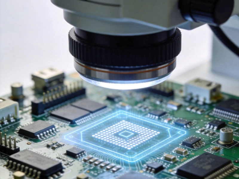
Avoiding Soldering Defects in High Frequency PCB Assembly for RF ApplicationsSeptember/11/2026
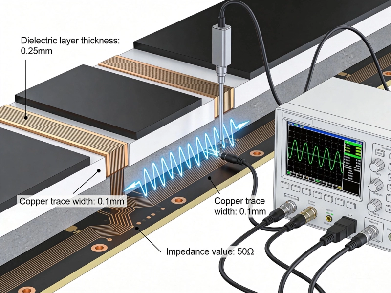
High Frequency PCB Fabrication: Managing Dielectric Constant (Dk) TolerancesJune/09/2026
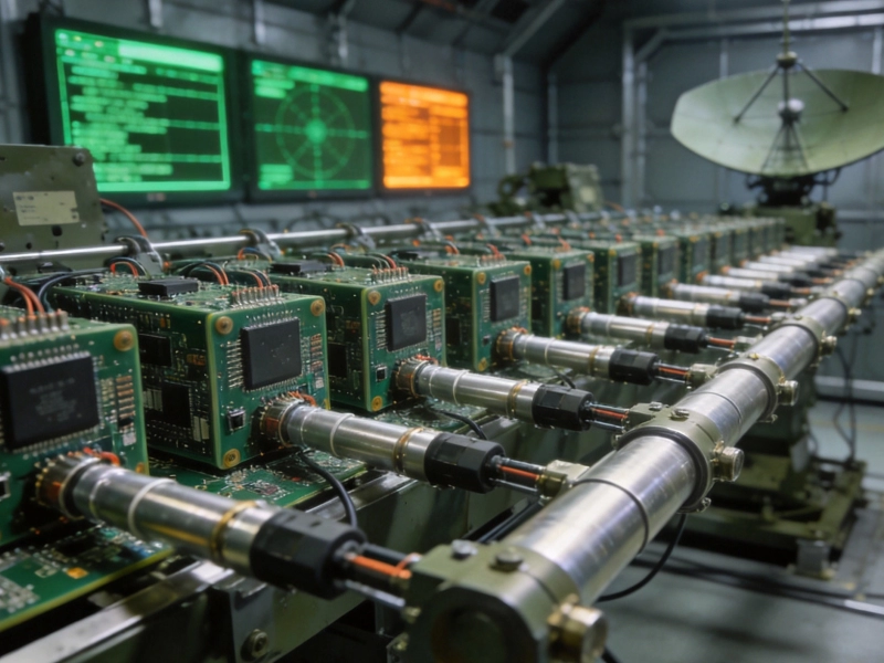
High Frequency PCB Applications for Military Radar and Electronic WarfareSeptember/18/2026
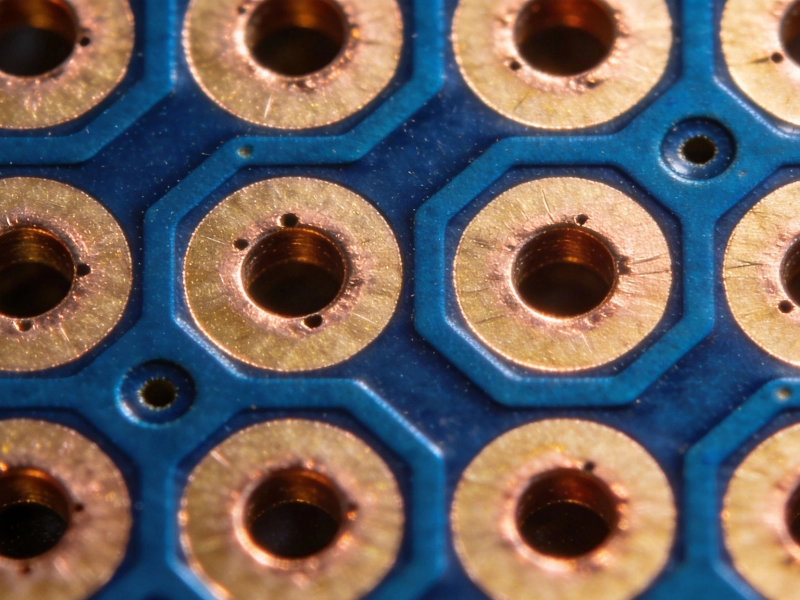
Laser Drilling and Microvias in Modern High Frequency PCB FabricationJuly/07/2026
The Impact of Surface Roughness on High Frequency PCB Fabrication QualityJune/27/2026