Open Nav
High frequency printed circuit boards represent some of the most demanding applications in modern electronics, serving as the backbone of 5G communications, Automotive Radar systems, satellite transceivers, and high-speed data networks. The choice between Surface Mount Technology and Through-Hole Technology assembly methods carries profound implications for Signal Integrity, manufacturing efficiency, and ultimate product performance. Understanding the fundamental characteristics, advantages, and limitations of each approach is essential for engineers designing high frequency circuits that must perform reliably in demanding operational environments.
The assembly technique selected for high frequency applications influences not merely manufacturing processes but also the electrical characteristics of completed circuits. Parasitic inductance, capacitive coupling, Impedance Control, and thermal management all depend on how components connect to transmission structures. These electrical consequences extend throughout product lifetime, affecting not just initial performance but long-term reliability under environmental stress and operational cycling. Making informed assembly decisions requires deep understanding of both manufacturing processes and high frequency electrical principles.
High Frequency Pcb Assembly operates under constraints fundamentally different from lower-frequency applications. At frequencies above 100 MHz, and particularly in microwave and millimeter-wave ranges, the electrical wavelengths become comparable to circuit dimensions, causing effects that can be ignored at lower frequencies to become dominant design considerations. Transmission line effects, Skin Effect losses, and parasitic reactances all intensify as frequency increases, making assembly technique selection one of the most consequential decisions in high frequency design.
The transition from analog to digital high-speed circuits has further complicated assembly requirements. Modern high frequency boards must handle both RF analog signals and rapid edge-rate digital signals, each presenting distinct assembly challenges. Rf Circuits require precise impedance matching and minimal discontinuities, while digital circuits demand consistent ground reference and controlled differential pair routing. Assembly techniques must support both requirements without compromise, often within the same physical board structure.
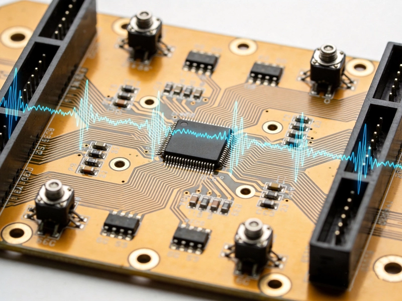
At high frequencies, every physical feature of a component attachment influences electrical performance. The length of a lead, the geometry of a pad, the thickness of a dielectric layer beneath a component—all become significant compared to signal wavelengths. A component lead that appears negligibly short at 1 MHz may introduce substantial series inductance at 10 GHz, degrading matching networks, creating resonance conditions, or radiating unwanted electromagnetic interference. Assembly technique determines how these parasitic elements manifest and whether they remain within acceptable bounds.
Thermal considerations also intensify at high frequencies. High frequency components often handle significant power in RF front-ends, generating heat that must dissipate through solder joints and thermal paths. The mechanical integrity of solder joints directly affects thermal resistance between component junction and board surface. Assembly techniques that create robust thermal paths enable reliable high-power operation, while those creating thermally resistive joints risk performance degradation and premature failure.
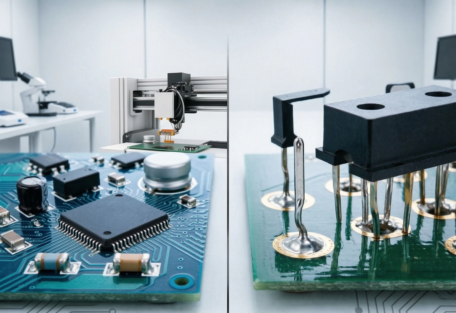
Surface Mount Technology has revolutionized electronics assembly, enabling the miniaturization and density improvements that define modern electronic products. SMT components mount directly onto board surfaces without requiring leads to pass through the board, creating connections between component termination and board pad through solder joints formed during reflow processing. This approach eliminates through-holes entirely for component mounting, reducing board complexity while enabling both sides of a board to accommodate components.
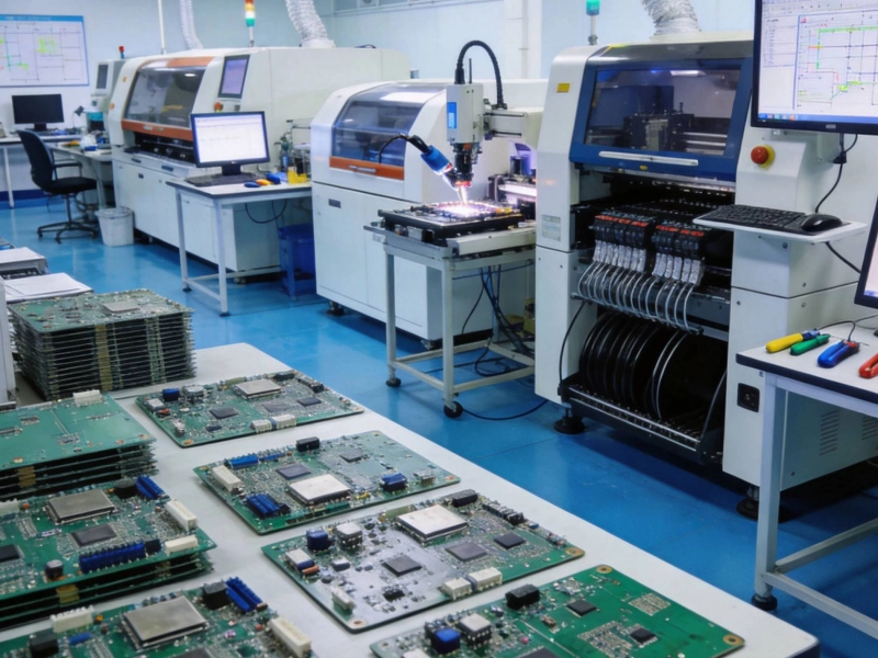
The SMT assembly process proceeds through controlled stages beginning with solder paste application through precision stencils, followed by Component Placement using automated equipment, and concluding with reflow soldering that melts paste and forms permanent joints. This highly automated process achieves placement accuracies measured in micrometers, handling components ranging from tiny 0201 passive devices to large area-array packages with thousands of terminations. The controlled, predictable nature of SMT processing enables high-volume production with exceptional quality consistency.
SMT provides substantial Signal Integrity benefits that make it the preferred choice for high frequency applications. The absence of through-holes eliminates the capacitive loading and inductive discontinuities that plated through-holes introduce. Component leads in SMT are measured in millimeters or less, compared to the centimeters that through-hole component leads often span. This reduced lead length directly translates to lower series inductance, minimizing parasitic reactance that degrades high frequency performance.
The planar nature of SMT termination provides superior grounding characteristics compared to raised through-hole leads. Ground connections made directly to surface pads on continuous reference planes achieve lower impedance than connections made through plated barrel holes. For high frequency circuits where ground impedance directly affects signal quality, this difference can be decisive. Devices designed for high frequency operation are increasingly available exclusively in surface mount packages specifically optimized for these electrical characteristics.
High frequency SMT assembly demands exceptional process control to achieve consistent results. Solder paste composition, stencil design, reflow profile, and atmospheric control all influence joint quality and electrical repeatability. For Rf Circuits where impedance tolerances may be ±5% or tighter, the dimensional consistency of solder joints directly affects electrical performance. Process capability studies and statistical process control help ensure that assembly variation remains within acceptable bounds.
Component selection for high frequency SMT requires attention to package geometry and termination design. Not all surface mount packages are created equal from a high frequency perspective. Components with shorter lead spans, multi-row terminations, or ground paddle configurations provide better electrical performance than simple chip terminations. RF-specific surface mount packages incorporate transmission line structures, ground plane extensions, and impedance-matching features that optimize high frequency performance while maintaining manufacturing efficiency.
Through-Hole Technology represents the original electronics assembly method, with component leads passing through holes drilled in the circuit board to make electrical connections on the opposite side. Despite the dominance of SMT in modern manufacturing, THT remains essential for numerous high frequency applications where its unique characteristics provide advantages that surface mount alternatives cannot match. Understanding when THT is appropriate requires appreciation for both its limitations and its irreplaceable benefits.
The THT assembly process involves inserting component leads into holes, typically followed by wave soldering where the board passes over a molten solder wave that flows up through holes to create connections. Alternative methods include hand soldering for prototypes and low-volume production, and selective soldering for mixed-technology assemblies where SMT and THT coexist. Each method presents distinct process characteristics that influence application suitability and manufacturing cost.
THT provides mechanical interconnection strength that surface mount joints cannot match. Component leads passing through holes and soldered in place create three-dimensional joints where solder fills the hole and encapsulates the lead. These joints withstand mechanical stress, vibration, and thermal cycling far better than surface mount joints, which attach only to pad surfaces. This mechanical advantage makes THT indispensable for applications in harsh environments where vibration, shock, or thermal stress would compromise surface mount reliability.
Automotive under-hood electronics, industrial motor controls, aerospace systems, and military equipment all depend on THT's mechanical robustness. Components in these applications experience sustained vibration, thermal cycling, and mechanical shock that would eventually fatigue surface mount solder joints. The mechanical anchoring provided by through-hole termination protects components against displacement and ensures long-term electrical reliability. This is why safety-critical and mission-critical electronics often mandate through-hole or mixed assembly approaches.
The electrical characteristics of through-hole terminations present significant challenges for high frequency operation. Lead length extending from component body through the board thickness—typically 1-2mm for standard components—introduces series inductance that becomes increasingly problematic at higher frequencies. A 2mm lead at 10 GHz presents approximately 1.3 ohms of inductive reactance, substantial enough to detune matching networks, create resonant conditions, and degrade signal quality in sensitive circuits.
Through-hole barrel capacitance also affects high frequency performance, particularly for circuits with high impedance nodes or sensitive RF inputs. The cylindrical geometry of plated through-holes creates parasitic capacitance to reference planes, loading circuits in ways that can be difficult to compensate. Designers must account for these parasitic effects through careful modeling and sometimes deliberate compensation networks. At frequencies above a few GHz, these effects often make through-hole termination impractical for RF circuits.
Systematic comparison of SMT and THT across the dimensions relevant to high frequency applications illuminates where each technology excels and where limitations constrain applicability. The comparison is not simply binary—many practical designs employ both technologies in hybrid configurations that capture benefits of each approach.
From an electrical perspective, SMT generally provides superior performance for high frequency circuits. The short lead lengths of surface mount terminations minimize series inductance, while the direct pad attachment to reference planes achieves low impedance ground connections. These characteristics enable surface mount RF circuits to operate at frequencies exceeding 100 GHz with minimal parasitic effects. Modern RF components including filters, amplifiers, and mixers are increasingly available exclusively in surface mount packages optimized for these frequencies.
THT electrical performance remains superior in specific scenarios involving high current-carrying components where the mechanical robustness of through-hole termination provides reliable power connections. High-power RF transistors, large magnetic components, and connectors that must withstand mechanical stress benefit from through-hole mounting. The key insight is that not all components in a high frequency assembly have identical electrical requirements—signal path components benefit from SMT while power and connector components may require THT.
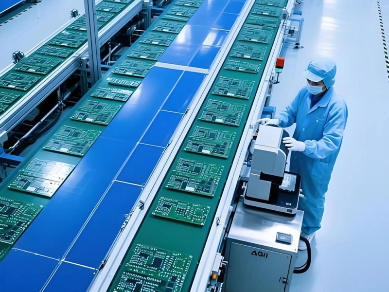
SMT manufacturing achieves exceptional cost efficiency through high automation and minimal material waste. Automated pick-and-place equipment assembles thousands of components per hour with labor costs amortized across massive production volumes. Boards require no drilling for component mounting, reducing manufacturing steps and eliminating drill tooling costs. The planar nature of surface mount components enables high-density layouts that reduce board area and material costs per function.
THT assembly incurs higher costs from drilling requirements, more complex processing, and typically lower automation levels. Each through-hole requires drilling, plating, and processing that adds to manufacturing cost and cycle time. Wave soldering requires larger equipment footprints and higher energy consumption than reflow processing. However, for applications where THT's mechanical advantages are essential, the cost premium may be justified by reliability requirements that surface mount cannot satisfy.
SMT enables design densities impossible with through-hole technology. Components mount on both board surfaces, with the only routing constraints being those imposed by signal integrity requirements rather than Component Placement limitations. Multi-row surface mount packages achieve pin counts in the thousands with footprints a fraction of equivalent through-hole packages. This density advantage translates directly to smaller end products and lower material costs per function.
THT density limitations result from the requirement for drilled holes on one or both board surfaces. Large component packages with multiple leads require substantial routing space, and both-sides placement becomes constrained by through-hole locations. While this density limitation restricts THT applicability for miniaturized products, it simplifies routing for high-power distribution where generous conductor sizing and spacing improve thermal management and current capacity.
The practical reality of most high frequency assemblies involves hybrid approaches that combine SMT and THT to capture the benefits of each technology. Mixed-technology boards require careful process planning to ensure that assembly sequences do not damage previously mounted components, but the resulting assemblies can achieve performance and reliability that neither technology alone provides.
Mixed-technology assembly requires careful sequencing to ensure manufacturing success. The standard approach mounts surface mount components first, as reflow processing is compatible with all components and creates no mechanical stresses that affect previously placed parts. Following SMT reflow, through-hole components are inserted and wave or selective soldering completes the assembly. This sequence ensures that high-value surface mount components are not exposed to potentially damaging wave soldering thermal profiles.
Selective soldering provides an alternative for mixed assemblies where wave soldering thermal exposure would damage temperature-sensitive surface mount components. Selective solder pots apply solder only to specific through-hole locations, avoiding thermal exposure to nearby surface mount components. While slower than wave soldering, selective processes enable mixed assemblies with sensitive components that wave soldering would damage. The higher process cost is justified by expanded component selection and design flexibility.
Successful mixed-technology design requires attention to component placement, thermal management, and assembly accessibility. Surface mount and through-hole components should cluster in distinct zones to simplify manufacturing and enable appropriate thermal profiles for each technology. Through-hole components requiring hand soldering or selective processing must have adequate access for operators or equipment positioning.
Thermal management considerations become more complex in mixed assemblies. The different thermal masses of surface mount and through-hole components affect solder joint formation during wave processing. Large through-hole components with high thermal mass may require adjusted wave profiles or preheating to achieve proper solder fill. Design rules should specify compatible component thermal characteristics and placement patterns that enable reliable processing.
Beyond the basic SMT versus THT comparison, high frequency assembly involves specialized techniques and considerations that determine ultimate circuit performance. These factors often distinguish professional high frequency manufacturing from general-purpose assembly services.
High frequency circuits require precise Impedance Control throughout signal paths, including component terminations. The impedance contribution of solder joints—affected by joint geometry, pad dimensions, and underlying dielectric—must be accounted for in transmission line design. Variations in solder volume or placement affect impedance, requiring process control that ensures joint consistency across production quantities.
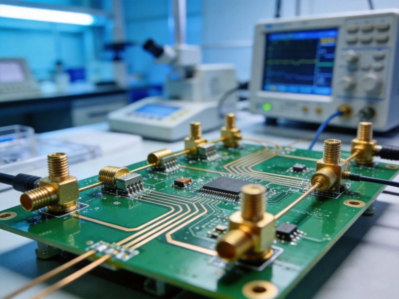
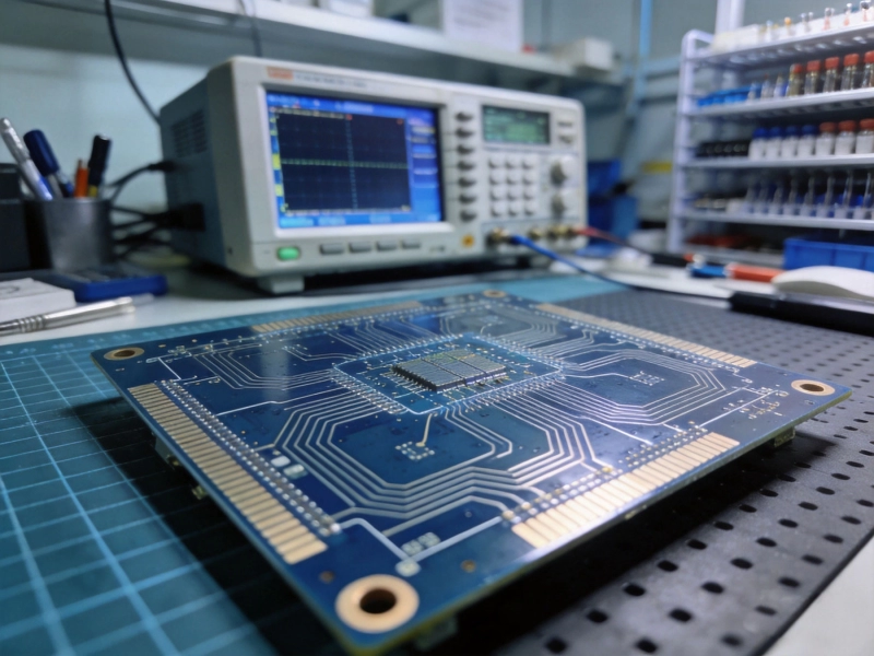
Measurement of high frequency impedance requires techniques beyond simple DC continuity testing. Time-domain reflectometry (TDR) characterizes impedance discontinuities including those at component terminations. Network analysis measures insertion loss and return loss that quantify high frequency performance. These measurements validate assembly quality and identify problems that electrical testing would miss.
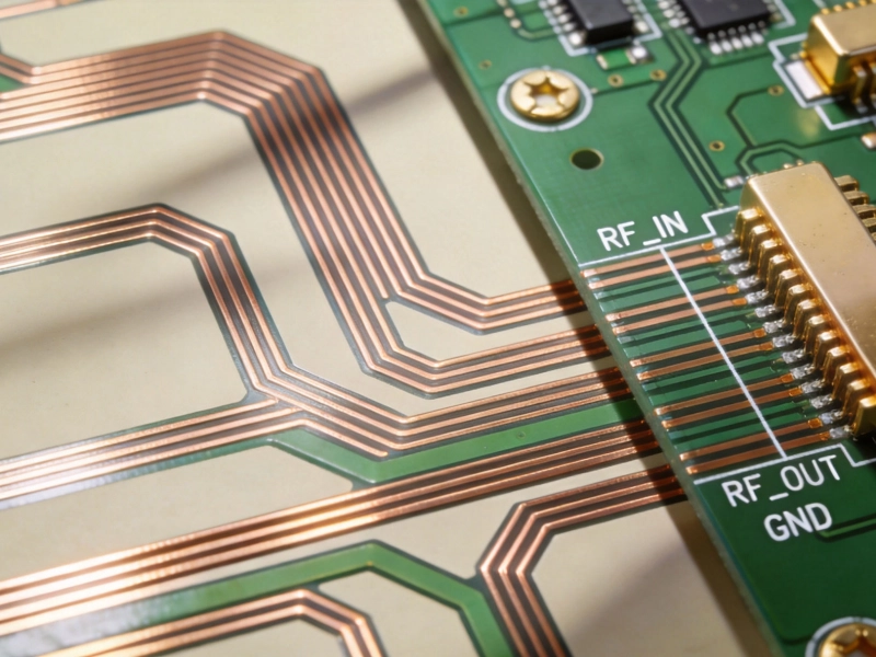
RF connectors present unique assembly challenges as mechanical interfaces between board circuits and external systems. Connector attachment must achieve both electrical continuity and mechanical robustness, often under demanding environmental conditions. Through-hole connectors provide mechanical strength for repeated mating cycles, while surface mount RF connectors offer lower profile and compatibility with high-density layouts.
Connector soldering for high frequency applications requires attention to solder fill, void content, and thermal management during assembly. Under-filled connector joints create thermal resistance that leads to performance degradation under power operation. Over-heating during assembly can damage connector Dielectric Materials or degrade plating quality. Professional RF assembly employs controlled processes with temperature monitoring and inspection to ensure connector reliability.
Selecting between SMT and THT for high frequency applications requires systematic evaluation of application requirements, manufacturing capabilities, and lifecycle expectations. The optimal choice depends on factors specific to each project rather than universal rules.
SMT is the clear choice for high frequency applications where maximum operating frequency exceeds several GHz, miniaturization is a priority, production volumes justify manufacturing investment, and environmental conditions fall within surface mount reliability bounds. 5G communications equipment, Automotive Radar sensors, and satellite systems overwhelmingly employ surface mount assembly for their high frequency sections because SMT provides the electrical performance these applications demand.
THT is appropriate for high frequency applications where mechanical robustness overrides electrical performance, through-hole components are required for specific functions such as high-power connections or ruggedized connectors, and production volumes are too low to justify specialized surface mount manufacturing. Industrial instrumentation, military communications, and aerospace systems often employ hybrid approaches where THT provides mechanical reliability for high-stress applications while SMT handles high frequency signal circuits.
The most sophisticated high frequency designs employ hybrid approaches that match assembly technology to component function. RF front-ends operating at frequencies above 10 GHz typically use surface mount for all signal path components while employing through-hole mounting for power components, connectors, and mechanical features. This targeted approach optimizes each function without compromise, achieving both electrical performance and mechanical reliability.
High frequency assembly technology continues advancing to meet the demands of emerging applications. Understanding these trends helps engineers anticipate future requirements and design assemblies that remain producible as technology evolves.
Advanced packaging technologies including flip-chip, embedded components, and fan-out wafer-level packaging offer new possibilities for high frequency assembly. These approaches eliminate traditional lead-frame or substrate interconnections, achieving ultra-short paths between active devices and circuit structures. While primarily developed for digital applications, these technologies increasingly appear in high frequency contexts where their electrical advantages outweigh added manufacturing complexity.
Integration of photonic and electronic assembly creates new challenges and opportunities. Optical interconnects operating at frequencies far exceeding electrical signals require hybrid assembly techniques combining precision optical alignment with RF electrical connections. These assemblies demand process capabilities beyond traditional electronics manufacturing, driving development of specialized equipment and techniques.
The choice between SMT and THT assembly for high frequency PCBs is not a binary decision but rather a spectrum of options that can be tailored to specific application requirements. Surface mount technology provides superior electrical performance through short lead lengths, low parasitic reactance, and compatibility with the controlled-impedance structures that high frequency circuits demand. Through-hole technology offers mechanical robustness essential for harsh environments and high-stress applications where electrical performance compromises can be tolerated.
Modern high frequency assemblies increasingly employ hybrid approaches that combine the electrical advantages of surface mount technology with the mechanical benefits of through-hole mounting. Careful process planning and design optimization enable these mixed assemblies to achieve performance and reliability that neither technology alone provides. The key is matching assembly techniques to component functions rather than applying one technology uniformly across entire assemblies.
As electronic systems continue pushing frequency boundaries higher while demanding greater miniaturization and reliability, assembly technology will continue evolving to meet these challenges. Engineers who understand the trade-offs between SMT and THT—and how to combine them optimally—will create the high frequency products that define next-generation communications, sensing, and computing systems. The assembly technique decision, made thoughtfully and implemented expertly, contributes fundamentally to product success.
SMT provides lower parasitic inductance due to shorter lead lengths, lower capacitive loading from direct pad attachment to reference planes, and superior ground impedance at RF frequencies. THT introduces series inductance from component leads passing through board thickness and barrel capacitance from plated through-holes. These parasitic effects become significant above 1 GHz, making THT generally unsuitable for sensitive high frequency applications.
Yes, mixed-technology assemblies combining SMT and THT are common in high frequency applications. The typical approach uses surface mount for high frequency signal path components while employing through-hole mounting for power components, connectors, and mechanical features. Careful process sequencing—mounting SMT first followed by wave or selective soldering for THT—enables reliable hybrid assemblies.
While no absolute threshold exists, SMT becomes clearly preferable above 5-10 GHz for sensitive RF circuits. Below these frequencies, THT may be acceptable depending on specific circuit requirements and environmental conditions. Above 20-30 GHz, THT is generally impractical for RF signal paths due to parasitic effects. The threshold also depends on circuit sensitivity—tight tolerance circuits require SMT at lower frequencies than less sensitive designs.
Reliable high frequency SMT joints require controlled solder paste composition and deposition through precision stencils, appropriate reflow profiles matched to component thermal mass, nitrogen atmospheres to reduce oxidation and improve wetting, and process monitoring to ensure consistency. Statistical process control maintains joint quality within electrical tolerance bounds. For critical applications, inspection including cross-section analysis verifies joint integrity.
SMT generally offers lower per-board costs for high-volume production due to automation efficiency and reduced manufacturing steps. THT costs more due to drilling, more complex processing, and typically lower automation levels. However, THT may reduce total system cost when mechanical reliability prevents field failures or when THT enables use of less expensive components or board materials.
The Challenges of High Frequency PCB Assembly: Handling Sensitive ComponentsMay/29/2026
High Frequency PCB Assembly Best Practices for 5G and RF ModulesJune/08/2026
Why Component Placement is Critical in High Frequency PCB AssemblyJune/25/2026
Pushing the Limits: Our Latest High Frequency PCB Capabilities for 6G ResearchJune/11/2026

How to Prepare Gerber Files for a Successful High Frequency PCB PrototypeJuly/02/2026
Common Pitfalls to Avoid During Your High Frequency PCB Prototype PhaseJune/18/2026
7 Key Factors to Consider When Choosing a High Frequency PCB ManufacturerMay/29/2026
Handling Sensitive ComponentsMay/29/2026