
High frequency printed circuit boards operate in demanding thermal environments where material properties directly impact circuit performance and reliability. From 5g Base Station transceivers to Automotive Radar systems, RF and Microwave Circuits depend on stable dielectric characteristics across temperature ranges. Understanding thermal stability in Pcb Materials helps engineers select substrates that maintain Signal Integrity under thermal stress, preventing performance degradation that corrupts data and compromises system reliability.
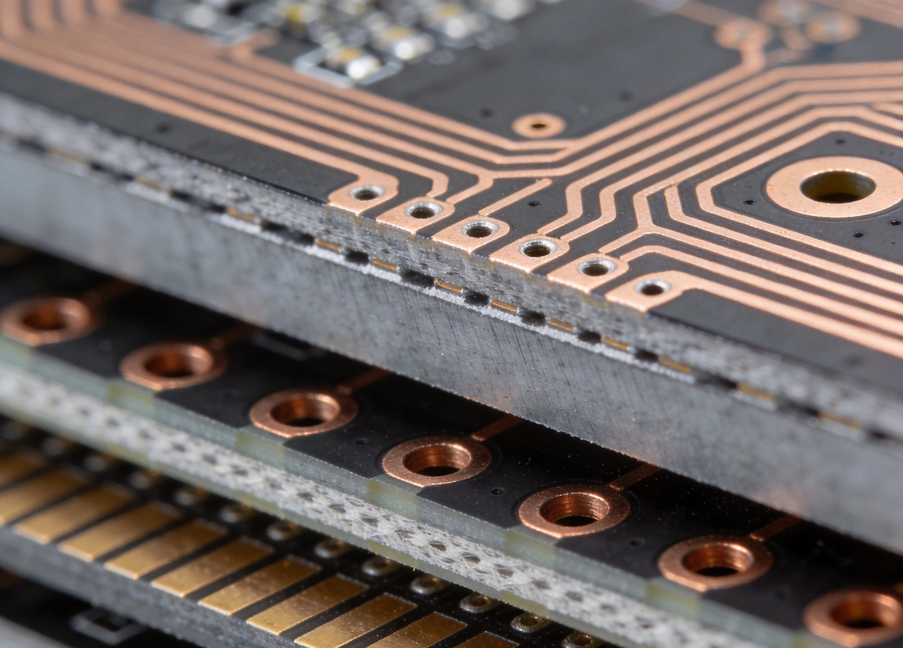
Pcb Materials respond to temperature through physical and chemical changes that affect electrical performance. These thermal behaviors define the operational envelope within which circuits function reliably.
Glass transition temperature (Tg) represents the temperature where polymer materials transition from rigid glassy states to soft rubbery states. Below Tg, polymer chains remain frozen in place, maintaining dimensional stability. Above Tg, molecular mobility increases dramatically, causing expansion, softening, and property changes that threaten circuit reliability.
Decomposition temperature (Td) marks where materials begin breaking down chemically, releasing volatiles and losing mass. Unlike Tg, decomposition causes permanent damage. Materials should never approach Td during normal operation, and significant margin below Td provides safety against thermal excursions.
Coefficient of thermal expansion (CTE) quantifies how dimensions change with temperature. Mismatched CTE between copper and dielectric creates mechanical stress during temperature cycling, potentially cracking vias, delaminating layers, or breaking circuit traces.
Thermal conductivity measures heat flow through materials. Higher conductivity helps dissipate heat from active components, maintaining lower operating temperatures. This property proves particularly important for power amplifiers and other heat-generating circuits.
RF and Microwave Circuits present unique thermal sensitivity because their performance depends on dimensional relationships at scales comparable to signal wavelengths. Even small changes affect electrical characteristics.
Dk temperature coefficient (Dk/Tc) describes how Dielectric Constant changes with temperature. Signal velocity in Transmission Lines depends on Dk, and Dk variations alter Characteristic Impedance and electrical length. For 28 GHz 5G signals with wavelengths measured in millimeters, dimensional changes of tens of microns shift phase relationships significantly.
Phase stability requirements
in phased array antenna systems demand consistent beam steering accuracy across temperature ranges. Dk variations introduce phase errors that mispoint beams, reducing system gain and potentially causing communication failures.
Impedance tolerance specifications typically require Characteristic Impedance within 5% of target. Temperature-induced Dk changes shift impedance outside acceptable windows, creating reflections that degrade signal quality and efficiency.
Dissipation Factor (Df) temperature coefficient affects signal attenuation through dielectric losses. As temperature increases, Df typically rises, increasing Insertion Loss. Power amplifiers heating substrates compound this effect, creating positive feedback loops where thermal run-away threatens circuit survival.
Signal Integrity margins in high-order modulation schemes like 64-QAM require low jitter and clean waveforms. Dielectric losses that increase with temperature corrupt constellation diagrams, reducing effective data throughput and increasing error rates.
high frequency PCB materials incorporate various compositions offering different thermal stability characteristics. Understanding these properties guides material selection for specific applications.
Glass transition temperatures in standard Fr-4 typically range from 130°C to 140°C, providing limited margin against operational temperatures. Lead-free assembly profiles reaching 260°C exceed these Tg values, requiring high-Tg Fr-4 alternatives or specialized materials.
Dk temperature sensitivity in epoxy-based materials proves significant, with typical Dk/Tc values of 200-400 ppm/°C. This sensitivity makes standard FR-4 unsuitable for demanding high frequency applications where phase stability matters.
Moisture absorption in FR-4 compounds affects thermal stability. Absorbed moisture vaporizes during thermal excursions, creating delamination risks and degrading electrical properties.
Enhanced glass transition temperatures in high-Tg materials reach 170°C, 180°C, or higher, providing greater margin against operational and assembly thermal stress. These materials maintain mechanical stability through demanding thermal profiles.
Reduced moisture sensitivity in high-Tg formulations improves thermal stability by minimizing absorbed water. Lower moisture content reduces vaporization risks during thermal cycling.
Improved Cte Matching in some high-Tg materials reduces mismatch between dielectric and copper, decreasing mechanical stress during temperature excursions.
Polytetrafluoroethylene (Ptfe) composites offer excellent high frequency performance with low loss and stable dielectric properties. However, Ptfe's mechanical softness and CTE mismatch with copper create assembly and reliability challenges.
Ceramic-filled PTFE materials improve mechanical properties and Cte Matching while maintaining PTFE's electrical advantages. Fillers like ceramic particles or glass fibers enhance dimensional stability without significantly degrading electrical performance.
Thermal stability range for PTFE materials extends well beyond most operational requirements, with decomposition temperatures exceeding 400°C. However, processing challenges and higher costs limit PTFE to applications demanding lowest losses.
Hydrocarbon resin systems provide cost-effective alternatives to PTFE while offering good high frequency performance. These materials balance electrical properties, thermal stability, and manufacturing practicality.
Thermal properties in hydrocarbon ceramics include Tg values of 200°C or higher, with lower Dk/Tc coefficients than FR-4. These characteristics suit demanding RF applications without PTFE's processing complexity.
Commercial availability of hydrocarbon ceramic materials from multiple suppliers provides design flexibility and reduces supply chain risk compared to specialized PTFE formulations.
Material specifications include various thermal metrics that guide selection and predict performance under thermal stress.
Measurement methods for Tg include differential scanning calorimetry (DSC) and thermomechanical analysis (TMA). Different methods may report slightly different values for the same material.
Operational guidelines recommend maintaining temperatures at least 20-30°C below Tg during continuous operation. This margin accommodates thermal excursions and ensures materials remain in stable glassy states.
Tg vs. performance correlation exists but isn't absolute. A higher Tg doesn't automatically indicate better high frequency performance. Electrical properties at operating frequencies matter equally alongside thermal characteristics.
5% weight loss temperature commonly reported as Td represents where significant thermal decomposition begins. Materials should maintain substantial margin below this temperature during normal operation.
Thermal degradation mechanisms include polymer chain scission, cross-linking, and filler release. These processes cause permanent property changes even before visible charring appears.
Processing considerations require understanding Td for assembly operations. Lead-free solder profiles peak near 260°C, requiring materials with Td significantly exceeding this temperature.
Composite metric combining Tg and Td provides thermal stability index. Higher values indicate broader temperature range between glass transition and decomposition.
Material comparison tool for evaluating high frequency substrates. Materials with higher TDI offer greater thermal design margin for demanding applications.
Coefficient of thermal expansion differences between PCB materials and copper create mechanical stress that threatens long-term reliability.
In-plane CTE in xy directions affects circuit dimensions and component spacing. CTE values for typical PCB dielectrics range from 12-70 ppm/°C, varying significantly with material composition.
Z-axis CTE through board thickness creates plated through-hole stress during thermal cycling. Vias experience hoop stress from surrounding dielectric expansion, potentially cracking barrel plating or creating intermittent opens.
Copper CTE of approximately 17 ppm/°C falls between typical dielectric values in xy directions but significantly lower than z-axis CTE. This mismatch drives reliability challenges in thermal cycling.
PTH barrel fatigue occurs from cyclic stress accumulation during temperature changes. Vias in high aspect ratio configurations prove particularly vulnerable to stress concentration at plating interfaces.
Microvia alternatives in HDI constructions exhibit different reliability characteristics. Laser-ablated microvias with thin dielectric columns experience less CTE mismatch stress than thick-dielectric through holes.
Thermal cycling test results guide material selection for applications expecting many temperature cycles. IPC testing standards define acceptance criteria for various reliability levels.
Material selection with CTE values closer to copper reduces mismatch stress. Fillers and reinforcement reduce xy CTE while maintaining electrical properties.
Stack-up design using hybrid constructions combines materials with complementary CTE characteristics. Careful layer arrangement optimizes overall board CTE behavior.
Via structure optimization including thermal relief patterns and optimized plating thickness distributes stress more evenly across via structures.
Heat dissipation in high frequency circuits requires systematic Thermal Management extending beyond material selection.
Thermal conductivity values for PCB materials range from 0.2 W/mK for standard dielectrics to over 2 W/mK for thermally-enhanced formulations. Higher conductivity improves heat spreading from power-dissipating components.
Metal core constructions including aluminum and copper substrates provide thermal conductivity exceeding 150 W/mK, enabling effective heat sinking directly from active devices.
Thermal via arrays conduct heat from surface components to internal planes or heat sinks. Via density, plating quality, and thermal interface materials determine thermal resistance through board stack-ups.
Component junction temperatures must remain below manufacturer-specified maximums for reliable operation. PCB thermal resistance determines whether circuits stay within safe operating windows.
Thermal simulation tools predict operating temperatures during design phases, enabling optimization before prototype fabrication. These tools model heat flow through boards, components, and thermal interfaces.
Thermal test coupons during production validation verify actual thermal performance against predictions, identifying discrepancies requiring design adjustments.
Different high frequency applications present different thermal stability requirements based on operating environments and performance demands.
Base station amplifiers generate significant heat requiring materials with high Tg and good thermal conductivity. Outdoor enclosures experience wide temperature ranges demanding stable electrical properties across extremes.
Phased array modules with integrated beamforming require phase-stable dielectrics maintaining beam pointing accuracy through thermal variations. Dk/Tc specifications become critical selection criteria.
Recommended materials include hydrocarbon ceramics with Tg exceeding 200°C and Dk/Tc below 50 ppm/°C. These balance cost, performance, and manufacturing practicality.
77 GHz and 79 GHz radar sensors demand ultra-stable dielectrics at millimeter-wave frequencies. Temperature ranges from -40°C to +125°C in automotive environments challenge material stability.
Thermal cycling endurance over vehicle lifetimes exceeds thousands of cycles, requiring materials proven through automotive qualification testing.
PTFE or ceramic-filled PTFE materials often specified for Automotive Radar due to superior thermal stability and consistent high frequency properties.
Space environments present extreme thermal cycling as satellites experience sun-side and shade-side temperature swings. Limited thermal cycling capability demands materials with proven space heritage.
Outgassing requirements for space applications require low volatile condensable materials preventing contamination of optical surfaces and thermal radiators.
High-reliability qualifications including thermal vacuum testing verify material stability for extended space missions.
Vector network analyzers and spectrum analyzers require exceptional phase stability for accurate measurements. Temperature chambers during calibration expose instruments to thermal variations.
Reference clock circuits in test equipment demand dielectrics maintaining consistent propagation delay across temperature ranges.
Lower-frequency applications like 6 GHz spectrum analyzers may accept standard high-Tg materials where 28 GHz applications require premium substrates.
Material datasheets provide thermal specifications requiring careful interpretation for design decisions.
Tg values require understanding measurement methods and interpretation. DSC measurements typically report onset Tg while TMA reports soften point, with different numerical values possible.
Td specifications should note measurement conditions including heating rate and atmosphere. Comparisons require consistent measurement protocols.
CTE values vary with temperature ranges, with values above Tg significantly exceeding those below glass transition. Ensure comparisons use consistent temperature ranges.
Technical data sheets provide nominal values while Supplier Qualification reports include statistical distributions and minimum guarantees.
Application notes from material suppliers offer guidance for specific applications, including recommended stack-ups and processing parameters.
Qualification test results including IPC testing demonstrate material performance against industry standards for thermal cycling, thermal shock, and bias humidity exposure.
Incoming inspection of critical materials verifies properties match specifications. Dimensional measurements, Tg verification, and visual inspection catch material variations affecting performance.
Process validation testing during manufacturing confirms materials perform as expected through assembly operations. Reflow profile optimization based on actual material response improves first-pass yields.
Application testing under representative thermal conditions validates material selection before committing to production. Prototype Testing in environmental chambers identifies issues before volume manufacturing.
Material selection balances performance requirements against cost constraints, with thermal stability representing significant but not sole selection criteria.
PTFE-based materials command significant premiums over FR-4 alternatives, with costs varying by filler content and manufacturer. Budget constraints may limit PTFE to most demanding applications.
Hydrocarbon ceramics provide mid-tier pricing between standard FR-4 and PTFE materials. These offer acceptable performance for many commercial high frequency applications.
Volume pricing reduces per-panel costs substantially for high-volume applications. Material qualification costs amortize more favorably in larger production volumes.
Manufacturing yield differences between materials affect total costs. Easier-to-process materials may reduce per-board costs despite higher material prices.
Reliability costs from field failures far exceed material cost differences. Applications where thermal excursions create field failures justify premium materials through reduced warranty and reputation costs.
System-level costs including Thermal Management hardware, testing requirements, and service intervals factor into material selection economics.
Thermal stability in high frequency PCB materials encompasses multiple properties affecting electrical performance, mechanical reliability, and long-term durability. Glass transition temperature, decomposition temperature, CTE matching, and Dielectric Constant temperature coefficients all influence material suitability for demanding RF and microwave applications.
Material selection requires balancing thermal stability against cost, manufacturing practicality, and electrical performance requirements. Standard FR-4 serves lower-frequency applications where thermal excursions remain limited, while PTFE-based and hydrocarbon ceramic materials address demanding applications from 5G infrastructure to automotive radar.
Understanding thermal specifications and their implications enables informed material selection. Tg provides mechanical stability guidance while Dk/Tc coefficients predict electrical performance variations. CTE matching considerations affect via reliability and long-term durability under thermal cycling.
Application-specific requirements drive material selection decisions. Thermal management requirements for power amplifiers differ from phase stability demands in phased array systems. Working with material suppliers and PCB manufacturers helps navigate selection trade-offs and optimize designs for specific application requirements.
Investment in thermally-stable materials pays returns through improved reliability, consistent performance, and reduced field failure costs. As high frequency applications continue expanding into demanding environments, material thermal stability becomes increasingly critical for system success.
For high frequency applications, Tg values exceeding 170°C provide adequate margin for lead-free assembly processes and operational thermal stress. Many hydrocarbon ceramic materials offer Tg values of 200°C or higher, while premium PTFE materials tolerate even higher temperatures. Select materials with Tg at least 30°C above maximum expected operating temperatures.
Dielectric constant typically increases with temperature, with coefficients ranging from 50-400 ppm/°C depending on material. This Dk/Tc shifts signal propagation velocity and characteristic impedance as temperature changes. For 5G and automotive radar applications, selecting materials with low Dk/Tc values below 50 ppm/°C maintains phase and impedance stability.
Standard FR-4 works for some high frequency applications below approximately 6 GHz where phase stability requirements remain modest. However, FR-4's higher Dk/Tc, lower Tg, and greater moisture absorption make it unsuitable for demanding applications like 5G, automotive radar, or aerospace systems where thermal stability directly impacts performance.
High frequency PCBs typically undergo thermal cycling testing per IPC standards, thermal shock testing, bias humidity exposure, and potentially extended temperature operation testing. Applications with specific environmental requirements may demand additional testing protocols validated to relevant industry or military specifications.
Create a comparison matrix including Tg, Td, CTE values (both xy and z-axis), thermal conductivity, Dk/Tc coefficient, and Dissipation Factor temperature coefficient. Weight criteria by application importance and evaluate materials against requirements. Supplier Qualification data and application notes provide additional comparison context beyond datasheet specifications.
Rogers vs. FR4: Choosing the Right High Frequency PCB MaterialsJune/12/2026

Top 5 High Frequency PCB Materials for 5G Base Station ApplicationsJuly/30/2026
How Dielectric Constant (Dk) and Loss Factor (Df) Affect High Frequency PCB MaterialsJuly/18/2026
Emerging Trends in High Frequency PCB Materials for Next-Gen CommunicationOctober/10/2026
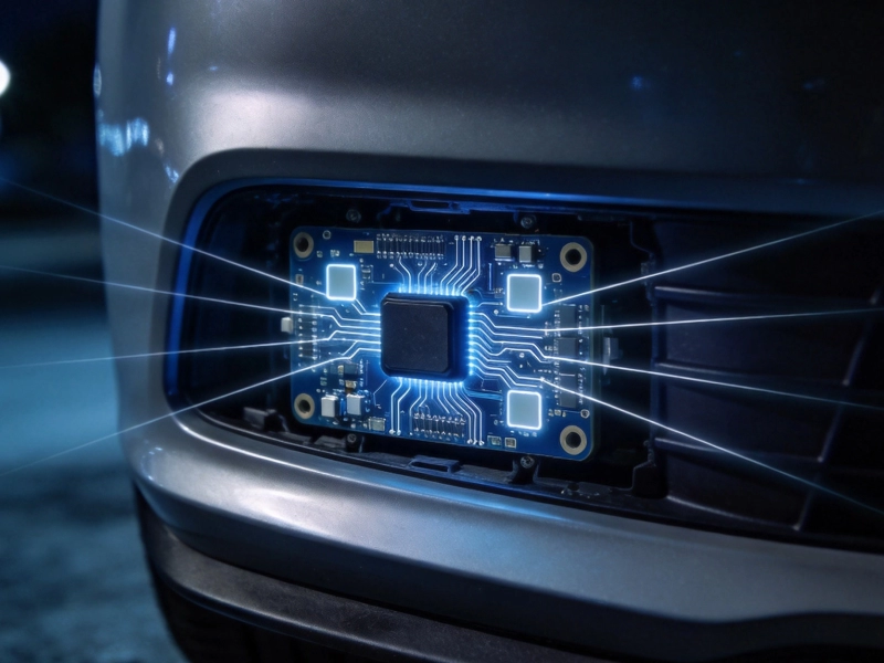
High Frequency PCB Materials for Automotive Radar: Durability and SpeedSeptember/26/2026
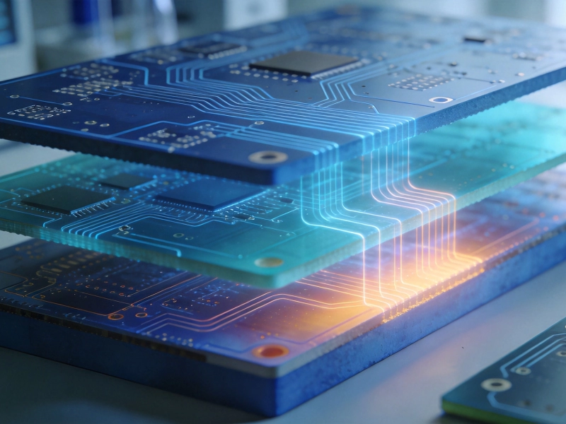
Cost vs. Performance: Selecting Budget-Friendly High Frequency PCB MaterialsSeptember/04/2026
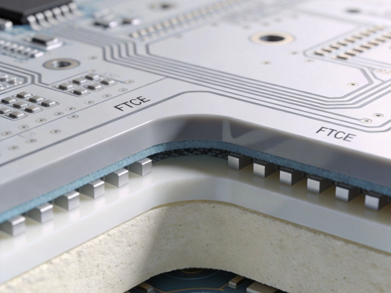
The Ultimate Guide to High Frequency PCB Materials: PTFE, Ceramic, and HydrocarbonJuly/08/2026
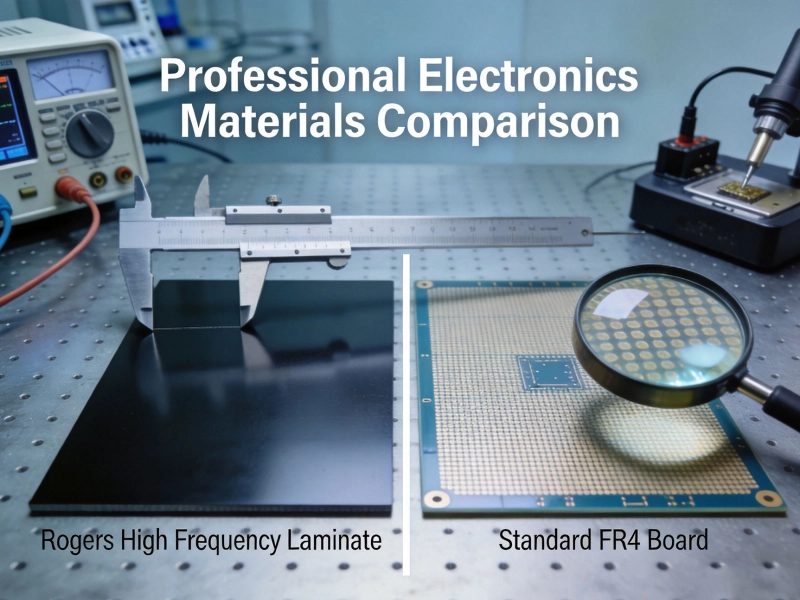
Choosing the Right High Frequency PCB MaterialsMay/29/2026