Open Nav

The demand for high-frequency printed circuit boards has surged dramatically with the rollout of 5G networks, millimeter-wave radar systems, and advanced Satellite Communications. These applications operate at frequencies ranging from several gigahertz to over 100 gigahertz, where traditional Fr-4 materials exhibit unacceptable signal losses and unstable dielectric properties. While high-performance materials like Rogers Ro4350b deliver the electrical characteristics required for these demanding applications, their cost can be prohibitive for complex multilayer designs. Mixed material lamination, combining high-frequency substrates with standard Fr-4 in strategic configurations, has emerged as the optimal solution for balancing performance and cost in advanced RF and microwave PCBs.
Manufacturing mixed material PCBs presents unique challenges that test the capabilities of even experienced fabricators. The combination of materials with different thermal expansion coefficients, glass transition temperatures, and resin systems requires precise process control and specialized expertise. Understanding these challenges and the strategies employed to overcome them reveals the true depth of capabilities required to produce reliable high-frequency mixed material boards.
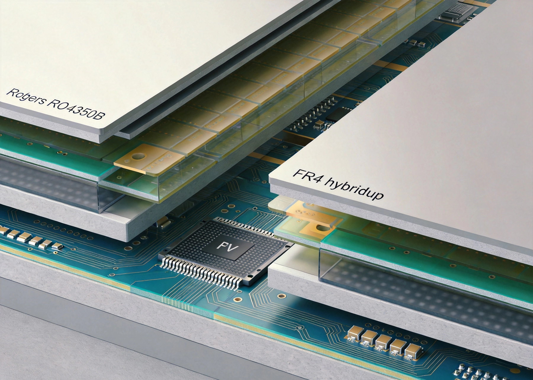
Pure high-frequency material constructions deliver optimal electrical performance but at significantly higher material costs, typically 3 to 5 times that of standard FR-4. For multilayer designs with 8, 12, or more layers, using high-frequency materials throughout the stackup becomes economically impractical for many applications. Mixed material lamination addresses this challenge by restricting high-performance materials to layers where RF performance is critical while using cost-effective FR-4 for power, ground, and low-speed signal layers.
The electrical benefits of this approach extend beyond simple cost reduction. Strategic placement of high-frequency materials ensures that critical RF traces, impedance-controlled differential pairs, and sensitive analog circuits operate in optimized dielectric environments. Meanwhile, digital control circuits, power distribution networks, and non-critical interconnects function adequately in standard FR-4, which offers excellent mechanical properties and well-established processing characteristics.
Hybrid stackups also enable thermal management optimization. High-frequency materials often have lower thermal conductivity than FR-4, creating challenges for heat dissipation in power amplifier applications. By integrating metal-core substrates or high-thermal-conductivity FR-4 variants with RF layers, mixed material designs can simultaneously address electrical and thermal requirements that would be difficult to satisfy with single-material constructions.
The foundation of successful mixed material lamination lies in selecting compatible material combinations. Rogers Ro4350b has emerged as the most popular high-frequency material for hybrid constructions due to its favorable balance of electrical performance, processability, and cost. With a Dielectric Constant of 3.48 and loss tangent of 0.0037 at 10 gigahertz, RO4350B provides stable electrical characteristics across a wide frequency range. Crucially, its ceramic-filled hydrocarbon resin system is compatible with standard FR-4 processing temperatures, enabling reliable lamination without specialized equipment.
Coefficient of thermal expansion matching represents a critical consideration in material selection. RO4350B exhibits X and Y axis CTE of approximately 10 to 14 ppm per degree Celsius, close to FR-4's typical 14 to 17 ppm per degree Celsius. This similarity minimizes thermal stress at material interfaces during fabrication and operation. The Z-axis CTE, which determines through-hole reliability during thermal cycling, also shows reasonable compatibility with appropriate prepreg selection.
Other high-frequency materials find application in specialized mixed material constructions. RO3003, with its PTFE-based ceramic-filled formulation, offers lower dielectric loss for millimeter-wave applications but requires more careful processing due to its softer mechanical characteristics. Taconic RF materials provide alternative formulations with different dielectric constants and loss characteristics, enabling customized solutions for specific frequency bands and impedance requirements.
Effective stackup design for mixed material PCBs requires careful planning of layer assignments and material placement. The most common configuration places high-frequency cores on the outer layers, where RF traces can be routed on optimized substrates while maintaining the mechanical stability of FR-4 in the core. This arrangement, often called a skin-core-skin construction, enables Controlled Impedance routing on the RF layers while leveraging FR-4 for internal power and ground planes.
Symmetric stackup design is essential for minimizing warpage in mixed material boards. Asymmetric constructions with high-frequency materials concentrated on one side create differential expansion forces during thermal processing that result in unacceptable bow and twist. Balanced placement of Rogers and FR-4 layers about the neutral axis, combined with copper area balancing across the stackup, maintains flatness within acceptable tolerances through fabrication and assembly.
Interface placement between different materials requires strategic consideration. Locating material transitions at internal layers rather than at surfaces reduces exposure to mechanical stress and environmental factors. Transition layers should incorporate appropriate prepreg materials that bond well to both adjacent substrates, creating reliable interfaces that resist delamination under thermal cycling and mechanical loading.
The lamination process for mixed material PCBs demands precise control of temperature, pressure, and time parameters to achieve reliable bonding without degrading material properties. Different resin systems have distinct curing characteristics, requiring careful selection of heating profiles that adequately cure all materials without overheating sensitive components.
Ramping rates during lamination heating cycles must be controlled to prevent thermal shock and ensure uniform temperature distribution across the multilayer stackup. Rapid heating can cause differential expansion between materials, creating internal stresses that manifest as delamination or dimensional instability. Controlled ramp rates of 1.5 to 3 degrees Celsius per minute allow uniform heating while maintaining material integrity.
Pressure application during lamination requires attention to the flow characteristics of different prepreg systems. High resin content prepregs designed for bonding to high-frequency materials may flow differently than standard FR-4 prepregs. Pressure profiles must ensure adequate resin flow to fill voids and create intimate contact at material interfaces without excessive squeeze-out that could create resin-starved areas or thickness variations.
Vacuum Lamination provides significant benefits for mixed material constructions by removing entrapped air and volatiles before pressure application. This reduces void formation at material interfaces and improves overall bond strength. Vacuum levels of 10 to 100 millibar during the early stages of lamination, followed by pressurization at cure temperature, produce optimal results for challenging mixed material combinations.
Coefficient of thermal expansion differences between materials represent the primary reliability concern in mixed material PCBs. While RO4350B and FR-4 show reasonable X and Y axis CTE matching, Z-axis expansion characteristics differ more significantly. This differential expansion creates shear stresses at plated through-holes that can lead to barrel cracking and electrical failure after thermal cycling.
Design strategies to mitigate CTE-related failures include minimizing the number of material transitions in the stackup and locating through-holes predominantly in single-material regions where possible. For holes that must traverse material interfaces, appropriate aspect ratio limits and copper plating thicknesses provide structural reinforcement against thermally induced stress.
Adhesive selection at material interfaces significantly impacts reliability. Specialized bonding films designed for high-frequency material lamination offer tailored CTE characteristics and enhanced adhesion to low-surface-energy substrates. These materials, such as Rogers RO4450F prepreg, are formulated specifically for bonding RO4000 series materials to each other and to FR-4, providing reliability that generic prepregs cannot match.
Thermal cycling testing validates the reliability of mixed material constructions under operational stress conditions. Standard qualification protocols subject sample boards to repeated temperature excursions between -40 and 125 degrees Celsius, monitoring via resistance for signs of barrel cracking or interface degradation. Boards designed and manufactured with proper CTE management demonstrate failure rates comparable to single-material constructions.
Maintaining precise Impedance Control across material transitions presents unique challenges in mixed material PCBs. Dielectric Constant variations between Rogers and FR-4 materials affect trace geometry requirements for target impedances. Careful modeling and simulation account for these variations during the design phase, ensuring that impedance-controlled traces maintain consistent characteristics even when routed across different substrate materials.
Microstrip and stripline configurations require different approaches in hybrid stackups. Surface microstrip lines on high-frequency outer layers benefit from the stable Dk of Rogers materials, while internal striplines may traverse multiple material types depending on layer assignments. Accurate field solver analysis of these complex configurations predicts impedance behavior and guides trace width and spacing adjustments.
Surface roughness of copper conductors becomes increasingly important at higher frequencies. High-frequency materials often specify low-profile copper foils that reduce conductor losses compared to standard foils used on FR-4. In mixed material boards, the transition between copper types at material interfaces requires careful process control to maintain consistent surface characteristics and avoid impedance discontinuities.
Producing reliable mixed material PCBs requires manufacturing capabilities beyond those needed for standard FR-4 boards. Advanced lamination equipment with precise temperature and pressure control enables the process windows required for multiple resin systems. Multiple lamination press configurations accommodate different material combinations without cross-contamination that could compromise material properties.
Drilling parameters must be optimized for the different hardness and cutting characteristics of high-frequency materials versus FR-4. PTFE-based materials in particular require specialized drilling protocols to prevent smearing and ensure clean hole walls for reliable plating. Laser drilling capabilities provide alternative approaches for microvias and small through-holes in challenging material combinations.
Plating processes must accommodate the surface chemistry of high-frequency materials, which often differs from FR-4. Plasma etching or chemical surface preparation ensures adequate copper adhesion and coverage on Rogers and similar substrates. Electroless copper deposition parameters may require adjustment to achieve reliable coverage on ceramic-filled hydrocarbon surfaces.
Verifying the integrity of mixed material PCBs requires specialized testing protocols that address the unique failure modes of hybrid constructions. Cross-sectional analysis reveals interface quality, plating integrity, and dielectric thickness consistency across material transitions. Microscopic examination of material boundaries identifies delamination, voids, or resin starvation that could compromise reliability.
Thermal stress testing validates the ability of mixed material boards to withstand assembly and operational temperature excursions. Solder float testing at 288 degrees Celsius exposes latent delamination or plating defects that might not be apparent in electrical testing. Extended thermal cycling to hundreds of cycles provides confidence in long-term reliability for mission-critical applications.
Electrical testing of high-frequency performance verifies that material properties meet design specifications. Vector network analyzer measurements of test coupons fabricated alongside production boards confirm dielectric constant and loss tangent values. Time-domain reflectometry traces impedance uniformity along Transmission Lines, identifying discontinuities at material interfaces or trace geometry variations.
Mixed material PCB capabilities enable a wide range of advanced applications across telecommunications, automotive, aerospace, and instrumentation markets. 5g Base Station antennas leverage hybrid stackups to combine high-performance RF layers for feed networks with FR-4 backing structures for mechanical support and digital control circuitry. The cost savings from mixed material designs make massive MIMO antenna arrays economically viable for widespread deployment.
Automotive Radar systems operating at 77 gigahertz for advanced driver assistance require the low dielectric loss of high-frequency materials for antenna elements and RF front-ends. Mixed material constructions integrate these sensitive Rf Circuits with FR-4-based power management and processor modules, delivering automotive-grade reliability at controlled cost. The thermal cycling resilience of properly designed mixed material boards meets the demanding requirements of under-hood automotive environments.
Satellite communication terminals and phased array systems benefit from the weight optimization enabled by mixed material designs. Eliminating unnecessary high-frequency material from non-critical layers reduces overall board weight and material cost while maintaining RF performance in signal paths. This weight reduction translates directly to launch cost savings and operational efficiency for space applications.
The evolution of high-frequency materials continues to expand the possibilities for mixed material PCB designs. New ceramic-filled formulations offer improved thermal conductivity for high-power RF applications while maintaining the low dielectric loss required for high-frequency operation. These materials enable integration of thermal management and RF performance in ways that were previously impractical.
Advanced lamination techniques such as sequential lamination and embedded component technology extend mixed material capabilities to increasingly complex designs. The ability to reliably integrate passive components within high-frequency layers while maintaining FR-4 for support structures opens new possibilities for miniaturization and performance optimization.
Simulation and modeling tools continue to improve prediction accuracy for mixed material behavior. Multi-physics simulations that couple electromagnetic, thermal, and mechanical analysis enable virtual prototyping of hybrid stackups, reducing the iteration cycles required to achieve optimal designs. These capabilities accelerate development schedules and reduce the cost of exploring innovative material combinations.
High-frequency PCB capabilities in mixed material lamination represent a critical enabling technology for advanced RF and microwave applications. The ability to combine high-performance Rogers materials with cost-effective FR-4 in reliable hybrid stackups delivers the performance required for 5G, radar, and satellite systems while maintaining economic viability. Success in this domain requires deep understanding of material properties, precise process control, and comprehensive validation capabilities that extend beyond standard Pcb Manufacturing.
As frequency requirements continue to increase and applications expand into new markets, mixed material lamination capabilities will only grow in importance. Investments in advanced lamination equipment, specialized processing expertise, and rigorous quality systems position capable manufacturers to meet these evolving demands. For designers navigating the trade-offs between performance and cost, mixed material PCBs offer a proven path to optimized solutions that neither pure high-frequency nor pure FR-4 constructions can match.
Understanding High Frequency PCB Capabilities: Line Width, Spacing, and Layer CountJune/28/2026
High Frequency PCB Capabilities for Aerospace and Defense ApplicationsJuly/17/2026
Why Advanced Testing Equipment Defines Top High Frequency PCB CapabilitiesJuly/07/2026
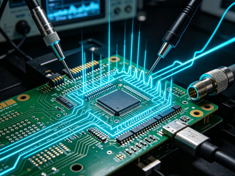
The Importance of Impedance Control in Our High Frequency PCB CapabilitiesSeptember/03/2026
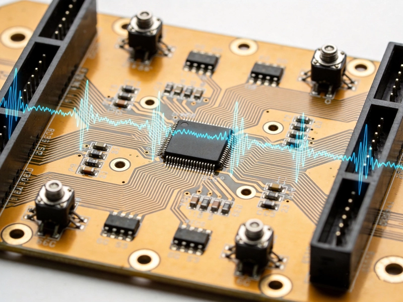
Pushing the Limits: Our Latest High Frequency PCB Capabilities for 6G ResearchJune/11/2026

How Our High Frequency PCB Capabilities Support High-Speed Data CentersAugust/08/2026
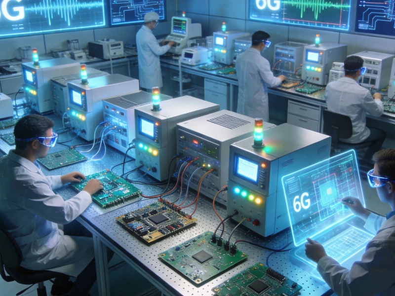
Our Latest High Frequency PCB Capabilities for 6G ResearchMay/29/2026
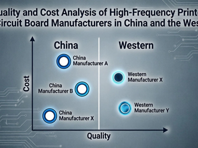
Quality and Cost Analysis of High-Frequency Printed Circuit Board Manufacturers in China and the WestJune/04/2026