
5G networks need more spectrum. Automotive Radar needs higher resolution. Satellite Communications need broader bandwidths. Every generation of wireless technology pushes the boundaries of what's possible with Pcb Materials. The problem: the materials that deliver the best high-frequency performance often cost five to ten times more than standard Fr-4.
For companies building products that must perform reliably at microwave frequencies while remaining cost-competitive, the question isn't simply "what's the best material?" It's "what's the best material for my specific application and budget?" This guide helps you navigate the tradeoffs and find the right balance between cost and performance.
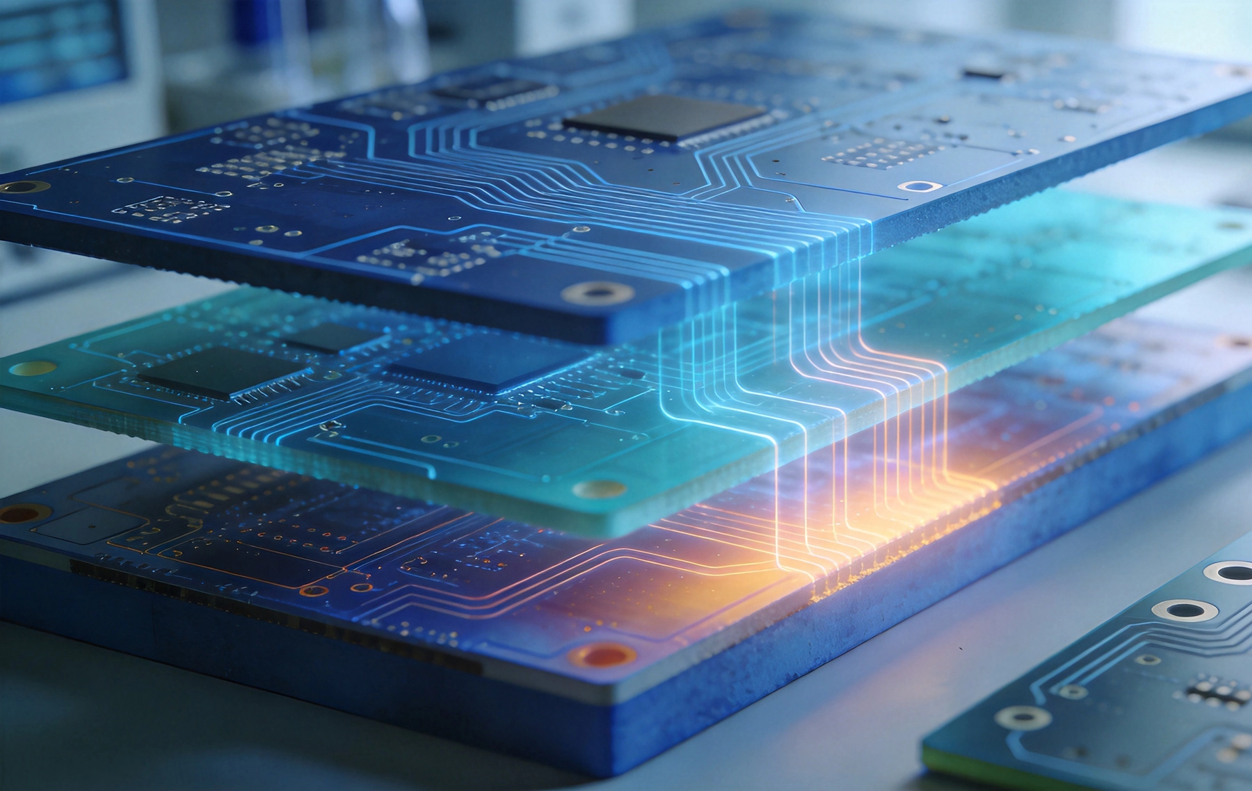
Before comparing materials, it's essential to understand what makes a material suitable for high-frequency applications. These electrical properties determine whether a material works for your design.
The Dielectric Constant, also called relative permittivity, determines how much the electric field is reduced when passing through the material. For high-frequency applications:
Typical high-frequency materials have Dk values ranging from 2.1 (Ptfe) to 10.2 (ceramic-filled), compared to 4.2-4.5 for standard Fr-4.
The Dissipation Factor (Df) measures how much energy is lost as heat when the material is subjected to an alternating electric field. This is often called loss tangent (tan δ).
High-performance materials have Df values of 0.001-0.004. Standard FR-4 can have Df of 0.02 or higher—at 10 GHz, FR-4 losses are 5-10x higher than premium materials.
High-frequency applications often involve significant thermal challenges:
Water has Dk of approximately 80—far higher than most Pcb Materials. Even small amounts of moisture absorption can significantly affect electrical performance:
High-frequency Pcb materials fall into distinct categories, each with different cost-performance profiles.
Polytetrafluoroethylene (Ptfe) materials deliver the best electrical performance but at premium cost.
Ceramic-filled PTFE combines PTFE's excellent electrical properties with improved mechanical properties and easier processing.
Hydrocarbon-ceramic composites offer a balance of performance and cost, processing like standard materials.
Enhanced FR-4 materials offer improved high-frequency performance at costs close to standard materials.
The "right" material depends heavily on your specific application. Let's analyze cost-performance tradeoffs for common high-frequency applications.
5G infrastructure operates at frequencies from 3.5 GHz to sub-6 GHz, with emerging bands above 24 GHz.
Requirements:
Recommended materials:
At 5G volumes, material cost matters enormously. RO4003C at approximately $15-25/sq ft delivers excellent performance at a fraction of the cost of PTFE materials.
77 GHz automotive radar requires the best possible high-frequency performance to achieve the resolution and range needed for safety-critical applications.
Requirements:
Recommended materials:
For automotive radar, performance typically outweighs cost considerations because safety and reliability are paramount.
Microwave backhaul links operate at 6-42 GHz, often requiring long signal paths and minimal loss.
Requirements:
Recommended materials:
Satellite applications demand the highest performance due to Signal Loss being multiplied by distance.
Requirements:
Recommended materials:
Consumer IoT and wearable devices operate at lower frequencies (sub-6 GHz) but require cost optimization for high volumes.
Requirements:
Recommended materials:
Material selection is one part of the cost equation. Design strategies can help maximize performance while controlling cost.
Use different materials for different layers based on signal requirements:
This approach requires careful attention to layer registration and thermal expansion matching between materials.
Properly designed Transmission Lines maximize Signal Integrity:
Maximize utilization of expensive material:
Different materials have different processing requirements that affect total cost.
Material source affects both cost and consistency.
Here's a practical decision framework for selecting high-frequency materials.
Use this simplified decision matrix:
| Material | Dk | Df @ 10GHz | Best Use | Relative Cost |
|---|---|---|---|---|
| FR-4 Standard | 4.2-4.5 | 0.020 | Digital only | $ |
| FR-4 High-Tg | 4.0-4.4 | 0.012-0.015 | Cost-sensitive RF | $$ |
| Isola I-Speed | 3.6 | 0.008 | High-speed digital/RF | $$ |
| Rogers RO4003C | 3.38 | 0.0027 | 5G, radar, RF | $$$ |
| Taconic RF-35 | 3.5 | 0.0018 | Cost-effective RF | $$$ |
| Rogers RO3003 | 3.0 | 0.0013 | 77 GHz radar | $$$$ |
| Rogers Ro4350b | 6.15 | 0.0037 | High-Dk RF | $$$ |
| Rogers RT/duroid 5880 | 2.2 | 0.0009 | Premium RF | $$$$$ |
Using the highest-performance material when a less expensive option would work wastes money. Many applications at 5-10 GHz work perfectly well with RO4003C or even modified FR-4.
Datasheet Df values are often measured at specific frequencies. Material performance can vary significantly across your operating range. Always check Df at your actual operating frequency.
A material with excellent nominal Dk but wide tolerance can cause more impedance variation than a material with slightly higher nominal Dk but tight tolerance. Specify Dk tolerance for critical applications.
Material cost is only part of total cost. Processing difficulty, yield, and fab house expertise all affect the final board cost. A more expensive material that processes easily may cost less overall.
Theoretical performance doesn't always match measured results. Always build and test prototypes to validate material selection before committing to production.
The materials landscape continues to evolve.
Integration of antenna elements directly in the package or substrate drives demand for materials that combine excellent RF performance with good Thermal Management and processability.
For extremely high frequencies, LTCC and other ceramic technologies offer performance advantages, though at higher cost and with different processing requirements.
Environmental concerns are driving development of halogen-free and more sustainable high-frequency materials. Early adopters of "green" high-frequency materials may face performance or cost tradeoffs.
New filler technologies are enabling materials with previously impossible combinations of properties—ultra-low loss with high Dk, or excellent thermal conductivity with good electrical performance.
Selecting High-frequency Pcb materials requires balancing electrical performance, processing requirements, and cost. The "best" material isn't the one with the lowest loss or the lowest price—it's the one that optimally meets your specific application requirements within your budget constraints.
Start with a clear understanding of your electrical requirements: operating frequency, acceptable loss, impedance tolerance, and environmental conditions. Then evaluate materials systematically, considering not just nominal performance but also Df variation with frequency, Dk tolerance, and processing characteristics.
For most commercial applications below 20 GHz, Rogers RO4000 series or equivalent materials deliver excellent performance at reasonable cost. Reserve premium PTFE materials for applications where their unique properties are genuinely needed.
Design for cost optimization: use hybrid stackups to minimize expensive material usage, optimize trace geometry for your material's properties, and validate selections with Prototype Testing. The extra upfront effort pays dividends in reduced material costs and improved first-pass yield.
Finally, remember that materials are one element of system performance. Even the best material can't compensate for poor design, and a good material used thoughtfully in a well-designed system can outperform an excellent material poorly applied.
Standard FR-4 can work for some applications up to 2-3 GHz with short signal paths. Above this frequency, the higher Dissipation Factor (Df ~0.02) causes unacceptable Signal Loss. For frequencies above 3 GHz, consider modified FR-4 or true high-frequency materials.
RO4003C is a hydrocarbon-ceramic composite that's FR-4 processable. RO3003 is ceramic-filled PTFE with lower loss but requires special processing. RO4003C offers the best value for most applications up to 20 GHz; RO3003 is preferred for 77 GHz automotive radar and similar ultra-high-frequency applications.
Temperature affects both Dk and Df. The temperature coefficient of Dk (TCDk) causes impedance and propagation velocity to shift with temperature. For wide temperature range applications, choose materials with stable Dk characteristics. PTFE materials generally have more stable temperature behavior than thermoset materials.
Several manufacturers produce materials competitive with Rogers. Taconic, Isola, and Nelco offer alternatives with similar performance. For most commercial applications, alternatives to Rogers work well. However, Rogers has extensive design support infrastructure and the broadest range of proven constructions, which can simplify development.
High-frequency material costs range from roughly the same as standard FR-4 (modified FR-4) to 10-50x more (premium PTFE). However, material is typically 20-40% of total PCB cost, so the total board cost increase is less dramatic. A board using RO4003C might cost 30-50% more than the same board on FR-4; using RT/duroid could triple the cost.
Need help selecting the right high-frequency material for your application? Our engineering team can provide recommendations based on your specific requirements.
Understanding Thermal Stability in High Frequency PCB MaterialsAugust/10/2026
The Ultimate Guide to High Frequency PCB Materials: PTFE, Ceramic, and HydrocarbonJuly/08/2026
Rogers vs. FR4: Choosing the Right High Frequency PCB MaterialsJune/12/2026
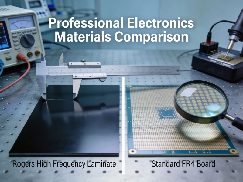
Choosing the Right High Frequency PCB MaterialsMay/29/2026
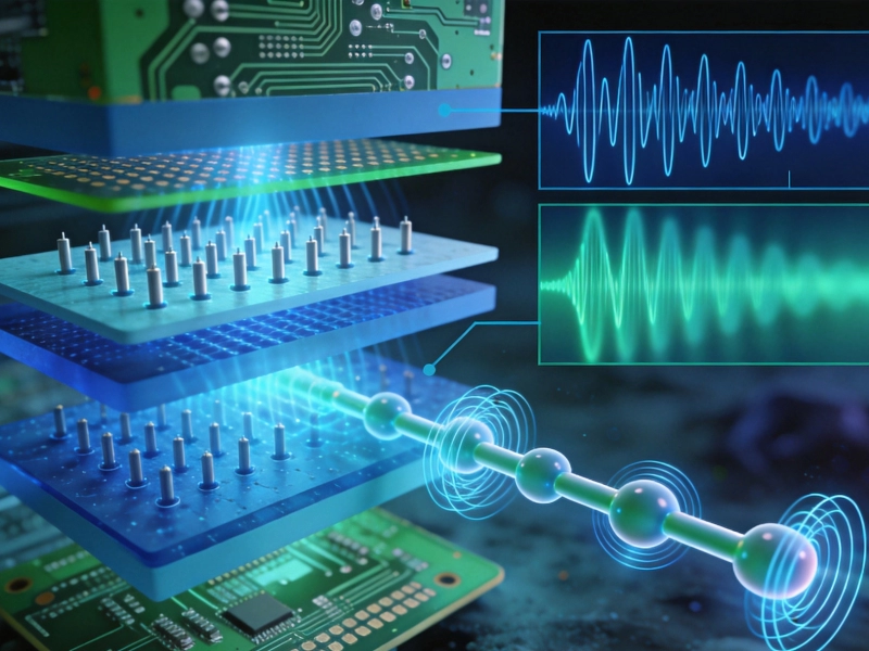
How Dielectric Constant (Dk) and Loss Factor (Df) Affect High Frequency PCB MaterialsJuly/18/2026
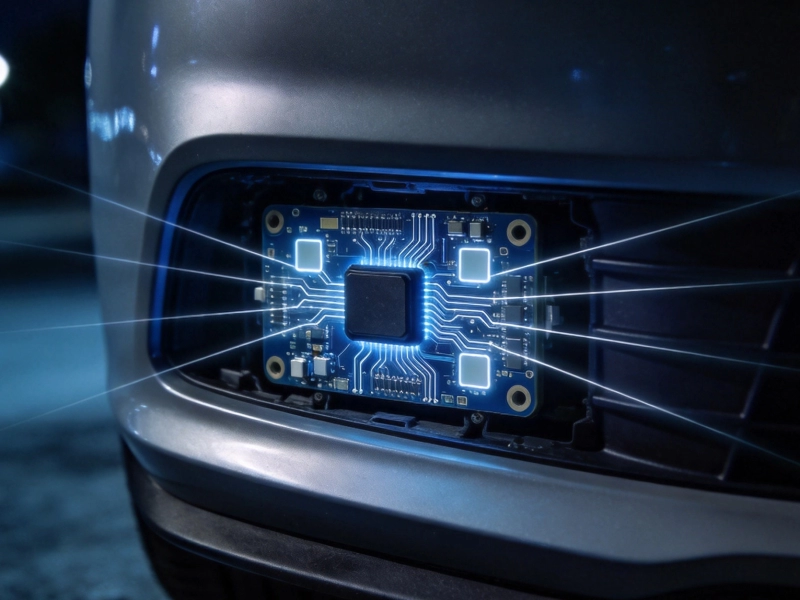
High Frequency PCB Materials for Automotive Radar: Durability and SpeedSeptember/26/2026
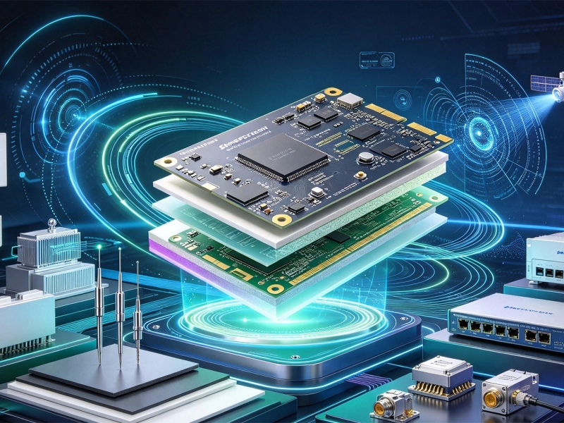
Emerging Trends in High Frequency PCB Materials for Next-Gen CommunicationOctober/10/2026
Top 5 High Frequency PCB Materials for 5G Base Station ApplicationsJuly/30/2026