Open Nav

Fifth generation wireless technology demands more from printed circuit board materials than any previous cellular standard. 5G base stations operate at frequencies ranging from sub-6 gigahertz up to Millimeter Wave bands above 24 GHz, with future expansions pushing toward 100 GHz and beyond. At these frequencies, the electrical properties of PCB substrates become as critical to performance as the active components mounted on them. Signal Loss, impedance variation, and thermal management all hinge on selecting the right material for each specific application within the base station architecture.
This article examines the five most widely adopted High Frequency Pcb Materials for 5g Base Station applications, analyzing their dielectric properties, thermal characteristics, fabrication considerations, and typical use cases. Understanding these materials helps engineers make informed decisions when designing RF front-end circuits, power amplifiers, and digital processing boards for next-generation cellular infrastructure.

Earlier generations of cellular technology, including 4G LTE, operated primarily below 6 GHz using relatively forgiving Pcb Materials. 5G changes this calculus fundamentally. The sub-6 GHz band already pushes the limits of standard Fr-4, but Millimeter Wave frequencies above 24 GHz make material selection absolutely critical.
Two material properties dominate high frequency performance. The Dielectric Constant, often called Dk or relative permittivity, determines how fast signals propagate through the material and how much capacitive effect the substrate introduces. Consistent Dk across the board and stable Dk over temperature are both essential for maintaining consistent impedance at high frequencies. The loss tangent, also called Dissipation Factor or Df, measures how much signal energy is lost as heat as it travels through the material. Lower loss tangent means less signal attenuation, which matters enormously at millimeter wave frequencies where even small losses accumulate over distance.
Rogers Corporation's RO4000 series has become the default choice for many 5g Base Station applications. The RO4003C and RO4350B grades offer a compelling combination of stable Dielectric Constant, low loss tangent, and excellent thermal performance at a price point that is accessible for high-volume infrastructure equipment.
RO4003C features a dielectric constant of 3.38 at 10 GHz, with variation of less than 50 parts per million per degree Celsius when properly engineered. This thermal stability means impedance tracks remain consistent across operating temperature ranges from arctic cold to desert heat. The loss tangent of 0.0027 at 10 GHz provides good Signal Integrity for frequencies up to approximately 20 GHz with careful design.
RO4350B offers slightly higher dielectric constant of 3.48, which allows slightly narrower traces for the same impedance compared to RO4003C. The trade-off is marginally higher loss tangent at 0.0037. Both grades are halogen-free and meet UL 94 V-0 flammability requirements, important for infrastructure equipment that must meet safety and environmental standards.
One of the RO4000 series' strongest advantages is its compatibility with standard Fr-4 fabrication processes. Unlike some high-performance materials that require specialized drilling, plating, or handling, RO4000 materials process like conventional laminates. This compatibility enables board manufacturers to produce complex multilayer boards combining RF materials with standard digital layers without investing in entirely separate production lines.
In 5G base stations, RO4000 series materials appear in power amplifier modules, RF front-end circuitry, antenna feed networks, and filter circuits. The material handles the moderate power levels common in active antenna systems without excessive Insertion Loss. Multiple-layer constructions enable integration of control circuitry and power distribution alongside the RF layers.
For the highest frequency 5G bands, particularly those above 20 GHz approaching millimeter wave territory, the Rogers RO3000 series with its PTFE ceramic formulation becomes the material of choice. These materials push dielectric constants higher to enable smaller circuits but compensate with exceptionally low loss and outstanding high-frequency performance.
RO3003 offers a low dielectric constant of 3.0 with loss tangent of just 0.001 at 10 GHz, extending to approximately 0.0013 at 30 GHz. This low loss makes RO3003 ideal for millimeter wave applications where Signal Integrity margins are razor-thin. RO3006 increases dielectric constant to 6.15 for applications requiring tighter field confinement, while RO3010 at 11.2 serves applications where miniaturization outweighs loss considerations.
The PTFE substrate provides excellent chemical resistance and moisture resistance, important for outdoor base station equipment exposed to humidity and temperature cycling. Thermal conductivity of approximately 0.6 W/mK helps with moderate heat spreading though supplemental thermal management is typically still required for power applications.
PTFE-based materials require more specialized processing than hydrocarbon ceramics. The material is softer than standard laminates and can compress during lamination if pressure is not controlled precisely. Via formation often requires plasma desmear rather than chemical processing, and some constructions use filler materials to improve mechanical stability. Designers specifying RO3000 materials should work closely with their fabricator to ensure proper process parameters.
RO3000 series materials dominate in 5G millimeter wave front-end modules operating above 24 GHz. Phased array antenna elements, RF connectors and adapters, and high-frequency test fixtures all benefit from the ultra-low loss characteristics. The higher Dk grades see use in filters and resonators where the dielectric constant enables size reduction.
Isola's I-Tera MT40 represents a newer entrant in the high-frequency material space, positioned as a mid-range option between standard FR-4 and premium Rogers materials. For base station applications that operate below 10 GHz, I-Tera MT40 offers a cost-effective path to adequate high-frequency performance without the premium pricing of PTFE-based materials.
I-Tera MT40 provides a dielectric constant of 3.45 at 10 GHz with loss tangent of 0.003. While not as low as RO4000 series, these values represent substantial improvement over standard FR-4 and are adequate for many sub-6 GHz 5G applications. The material maintains stable electrical properties across typical operating temperature ranges, with published data showing Dk variation within acceptable bounds.
One distinctive feature of I-Tera MT40 is its compatibility with lead-free assembly processes. As RoHS compliance has become mandatory for most electronics, materials that withstand multiple lead-free reflow cycles without degradation have gained importance. I-Tera MT40 is engineered specifically for lead-free assembly reliability.
Like RO4000 series, I-Tera MT40 processes using standard FR-4 equipment and procedures. This compatibility simplifies Supply Chain Management and enables fabricators to build mixed-material boards combining high-frequency and standard layers. The material drills and plates consistently, with reliable via formation using conventional techniques.
I-Tera MT40 serves digital processing boards, control interfaces, and lower-frequency RF sections in 5G base stations. It is particularly popular for applications combining digital and RF functions on the same board, where one material serves both purposes. The cost advantage becomes significant for large base station volumes where material costs directly impact product economics.
Panasonic's Megtron 6 occupies the high-performance digital laminate space while still offering adequate high-frequency characteristics for many 5G applications. This material prioritizes ultra-low transmission loss for high-speed digital signals, but those same characteristics translate to reasonable performance for RF applications below 10 GHz.
Megtron 6 achieves an extremely low Dissipation Factor of 0.002 at 1 GHz, which scales favorably compared to competing materials at higher frequencies. The material's strength lies in its loss performance for digital signals at data rates up to 25 Gbps and beyond. Dielectric constant of 3.4 to 3.6 depending on exact grade provides consistency for Controlled Impedance designs.
Beyond electrical performance, Megtron 6 offers exceptional thermal performance with Glass Transition Temperature exceeding 200 degrees Celsius and decomposition temperature above 300 degrees Celsius. This thermal margin provides headroom for high-power applications and ensures reliability through thermal cycling.
Megtron materials process using standard epoxy laminate techniques, though the low-profile glass styles required for optimal electrical performance may require attention to lamination parameters. The material bonds reliably with standard prepreg and builds successfully into complex multilayer constructions.
In 5G base stations, Megtron 6 appears primarily in high-speed digital boards including processing units, interface cards, and backhaul communication modules. The material also serves mixed-signal applications where digital switching noise and RF performance must coexist on the same board. For pure RF applications above 10 GHz, other materials typically perform better.
Taconic's RF-35 material fills a niche for cost-sensitive applications that still require meaningful high-frequency performance. As a hydrocarbon ceramic material, RF-35 offers PTFE-like electrical characteristics at a lower price point while maintaining reasonable processability.
RF-35 provides dielectric constant of 3.5 at 10 GHz with loss tangent of 0.0018. These values approach RO4000 series performance at a lower price level. The material maintains stable electrical properties across temperature and frequency ranges suitable for most sub-10 GHz wireless applications.
Mechanical properties include good dimensional stability and moderate thermal conductivity. The material handles standard multilayer construction with appropriate process controls and provides reliable performance in environments with moderate thermal demands.
Hydrocarbon ceramics like RF-35 process more like standard FR-4 than pure PTFE materials. Drilling and plating proceed using conventional parameters, and the material bonds reliably with standard prepreg systems. This processability advantage makes RF-35 attractive for manufacturers without specialized high-frequency processing capabilities.
RF-35 serves cost-optimized RF front-end designs, antenna feed networks for smaller cell installations, and general wireless infrastructure applications where extreme frequency performance is not required. The material has found adoption in small cell and picocell equipment where volume economics favor lower material costs.
When selecting among these materials, the choice ultimately depends on the specific frequency band, power requirements, volume expectations, and performance margins of each application. A summary comparison helps clarify the trade-offs.
For millimeter wave applications above 24 GHz, Rogers RO3000 series is essentially the default choice despite its higher cost and more demanding fabrication requirements. No other readily available material matches its combination of low loss and stable electrical properties at these frequencies.
For sub-6 GHz 5G applications, Rogers RO4000 series offers the best balance of performance and processability for most applications. Isola I-Tera MT40 and Taconic RF-35 provide cost-effective alternatives where the extra performance margin of Rogers materials is not required.
For digital-dominated applications, Panasonic Megtron 6 provides excellent high-speed digital performance while remaining adequate for co-located RF functions. The material's thermal margin provides reliability benefits for power-intensive applications.
Material selection is necessary but not sufficient for successful 5g Pcb design. The interplay between material properties and design practices determines final performance. Trace geometry, layer stack-up, via treatment, and Component Placement all influence how well a board performs relative to the material's theoretical capabilities.
Controlled Impedance design becomes more critical at higher frequencies. The dielectric constant of even high-quality materials varies somewhat with frequency, and this variation must be accounted for in impedance calculations. Working with your fabricator to validate impedance targets through test coupons provides confidence that the manufactured board matches the designed performance.
Thermal management deserves attention even for relatively low-power Rf Circuits. High-frequency signals create losses that manifest as heat, and temperature rises affect both electrical performance and long-term reliability. Incorporating thermal relief strategies, whether through board design or supplemental cooling, protects both the material and the components mounted on it.
The five materials covered here represent the mainstream options for 5G base station applications, but they do not exhaust the available choices. Specialty materials from other manufacturers fill additional niches, and new formulations continue to enter the market as 5G technology evolves. Staying current with material developments requires ongoing engagement with material suppliers and board fabricators.
For engineers designing 5G infrastructure, the decision path starts with frequency band and power level, narrows to compatible materials based on performance requirements and fabrication capabilities, and ultimately resolves through trade-off analysis of cost, availability, and manufacturing risk. The materials reviewed here provide a solid starting point for that analysis across the full spectrum of 5G base station applications.
Standard FR-4 is generally not suitable for active 5G Rf Circuits, particularly above 3 GHz. The high loss tangent and variable dielectric constant of FR-4 cause unacceptable signal attenuation and impedance variation. FR-4 remains acceptable for digital control circuitry and power distribution in base stations, but RF layers should use high-frequency materials.
For sub-6 GHz applications, Isola I-Tera MT40 and Taconic RF-35 offer cost advantages over Rogers materials while providing adequate performance. The trade-off is higher loss and potentially less stable electrical properties. Evaluate whether the performance margin of premium materials justifies the cost premium for your specific application.
Moisture absorption increases dielectric constant and loss tangent, degrading RF performance. PTFE materials like RO3000 series resist moisture absorption well. Hydrocarbon and epoxy-based materials absorb more moisture and may require protection through conformal coating or design margins that account for humidity exposure in outdoor base station environments.
PTFE materials typically require plasma desmear for via formation rather than chemical processing, different lamination parameters, and potentially specialized handling. Hydrocarbon ceramics like RO4000 series process nearly identically to FR-4. Specify your material to the fabricator early so they can configure appropriate processes.
Request material certifications with lot traceability from your fabricator. For critical applications, include test coupons on panels that enable verification of dielectric constant through electrical testing. Cross-sectional analysis can confirm layer construction and material identity.
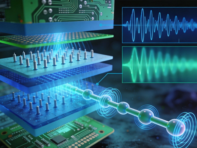
How Dielectric Constant (Dk) and Loss Factor (Df) Affect High Frequency PCB MaterialsJuly/18/2026
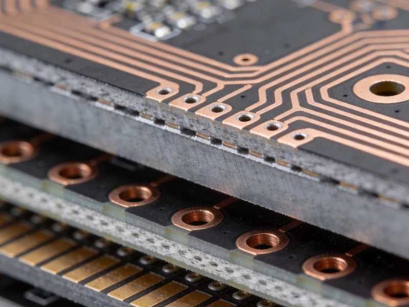
Understanding Thermal Stability in High Frequency PCB MaterialsAugust/10/2026
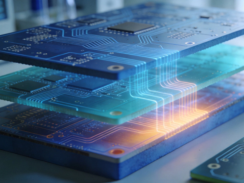
Cost vs. Performance: Selecting Budget-Friendly High Frequency PCB MaterialsSeptember/04/2026
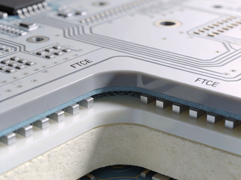
The Ultimate Guide to High Frequency PCB Materials: PTFE, Ceramic, and HydrocarbonJuly/08/2026
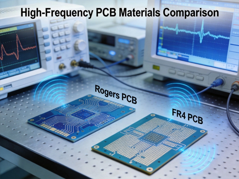
Rogers vs. FR4: Choosing the Right High Frequency PCB MaterialsJune/12/2026
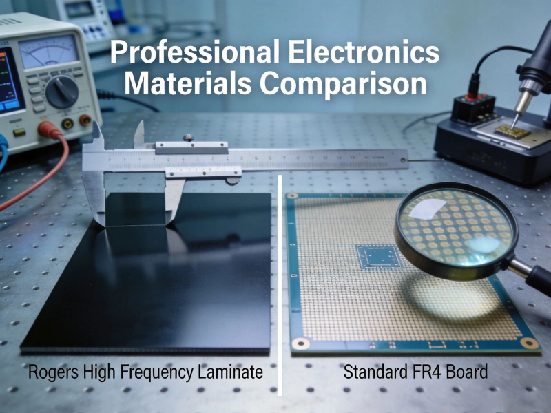
Choosing the Right High Frequency PCB MaterialsMay/29/2026
Inside the Factory: What to Look for in a High Frequency PCB Manufacturer's FacilityAugust/03/2026
Key High Frequency PCB Knowledge for Successful RF Circuit DesignSeptember/07/2026