Open Nav

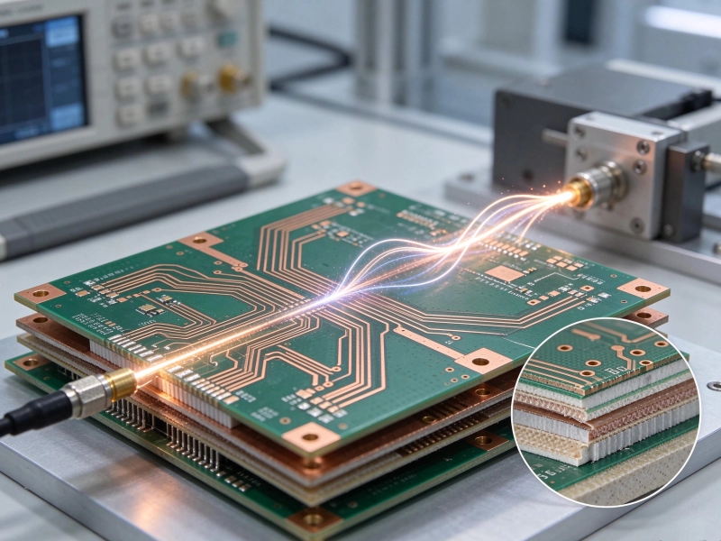
Designing circuits for RF and microwave frequencies demands a fundamentally different approach to Pcb Material Selection than designing for digital logic. At low frequencies, the choice of substrate matters little; Fr-4 works adequately for almost everything from power supplies to microcontrollers because the electrical behavior of the circuit is dominated by the components, not by the properties of the board material. At high frequencies, everything changes. The Dielectric Constant of the substrate directly determines the propagation velocity and impedance of Transmission Lines. The Dissipation Factor determines how much signal energy is lost as heat as it travels down the trace. The thermal stability of these properties determines whether the circuit performs consistently across the operating temperature range. And the dimensional stability of the substrate affects whether the fabricated board matches the designed dimensions, which at microwave frequencies can mean the difference between a circuit that works and one that is hopelessly detuned. Understanding how Dielectric Materials behave at high frequencies, and how to select the right material for a specific application, is an essential competency for anyone designing circuits that operate above approximately 1 GHz.
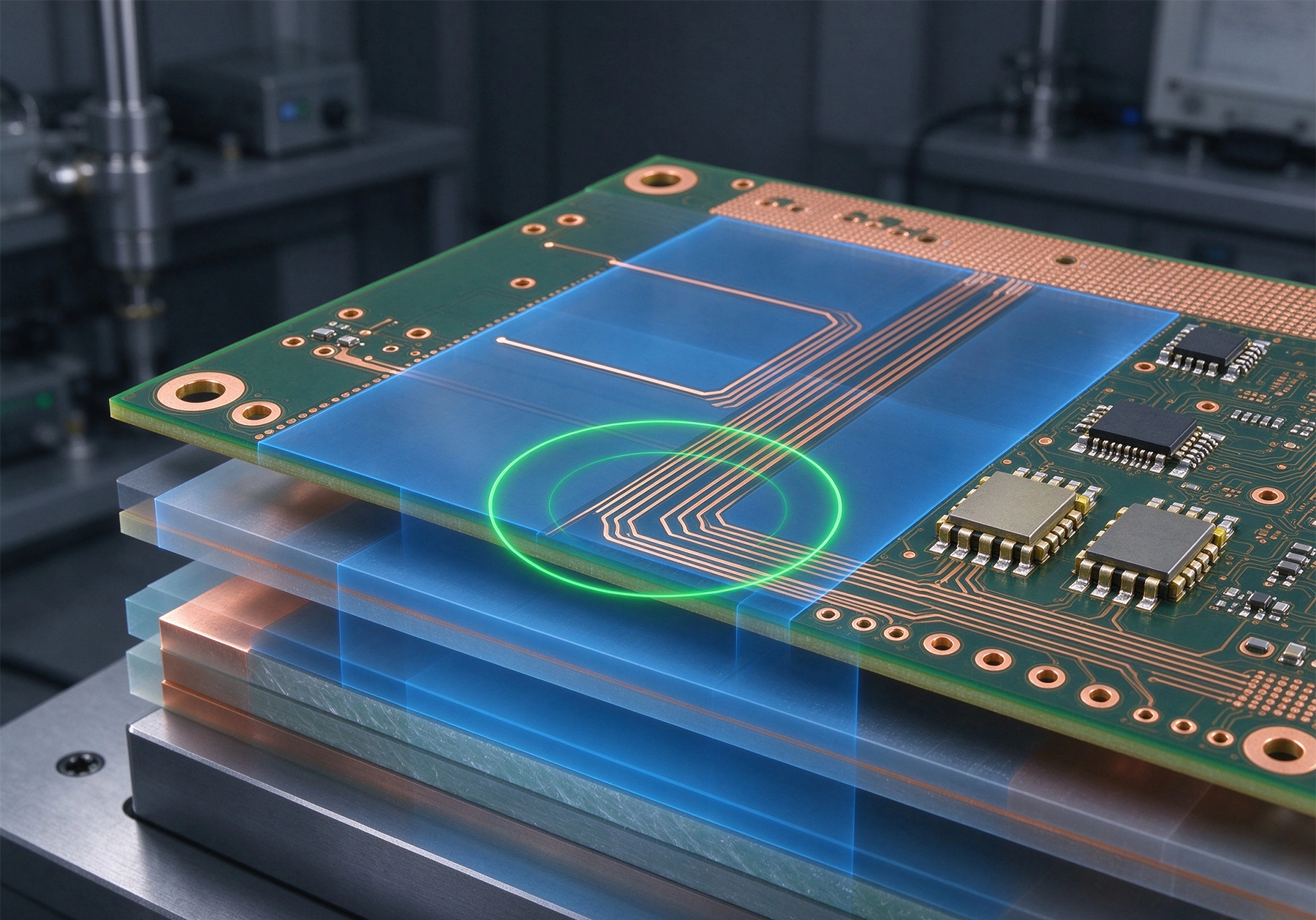
The Dielectric Constant, often expressed as Dk or relative permittivity, describes how the substrate material affects the electric field in a capacitor formed by the substrate between two conductors. In a PCB Transmission Line, the dielectric constant determines the effective capacitance per unit length of the line, which in turn determines the Characteristic Impedance and the propagation velocity. A trace on a substrate with Dk of 4.2, like standard Fr-4, will have a different impedance and a slower propagation velocity than the same trace on a substrate with Dk of 2.9, like a ceramic-filled hydrocarbon material. At low frequencies, this difference matters only for precise timing applications. At microwave frequencies, the wavelength of the signal is short enough that even small variations in propagation velocity cause significant phase errors, and the impedance must be controlled to tight tolerances to prevent reflections that degrade signal quality.
Dissipation Factor, also called loss tangent and expressed as Df or tan delta, describes the dielectric losses in the substrate material. When an alternating electric field passes through a dielectric, some of the energy is converted to heat by the molecular friction as the dipoles in the material struggle to follow the alternating field. The dissipation factor quantifies the ratio of energy lost to energy stored per cycle. A material with high Df absorbs more signal energy and converts it to heat, reducing the signal amplitude as it travels along the Transmission Line. At low frequencies, dielectric loss is negligible compared to conductor loss and radiation loss. At microwave frequencies, dielectric loss can dominate the total loss budget, particularly for long Transmission Lines or high-Q resonant structures.
The frequency dependence of both Dk and Df is critical for wideband applications. Most Dielectric Materials exhibit some variation of their electrical properties with frequency, and this variation is not always linear or predictable. Ptfe-based materials tend to have more stable Dk and Df across wide frequency ranges than epoxy-based materials, which makes Ptfe preferable for wideband applications like broadband amplifiers or ultra-wideband radar. The designer must know the Dk and Df at the actual operating frequency, not just at the datasheet test frequency, to accurately model the circuit behavior.
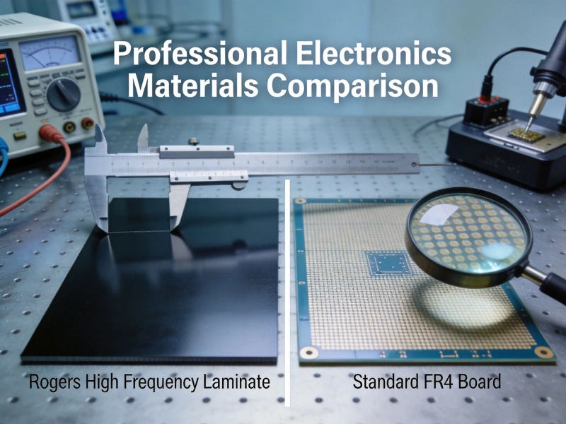
FR-4 epoxy-glass laminate is the workhorse substrate of the PCB industry because it offers an attractive combination of low cost, good mechanical properties, adequate electrical performance for digital applications, and mature manufacturing infrastructure. For RF and microwave applications, FR-4 has well-known limitations that constrain its usefulness to frequencies below approximately 5 GHz in most configurations.
The Dk of standard FR-4 ranges from approximately 4.2 to 4.8 depending on the resin content, glass weave style, and frequency. This relatively high Dk means that Microstrip traces on FR-4 are more tightly coupled to the reference plane and have slower propagation velocity than traces on lower-Dk materials. The higher Dk also means that the wavelength at a given frequency is shorter on FR-4 than on lower-Dk materials, which can be either an advantage or a disadvantage depending on the application. The shorter wavelength enables more compact resonators and filters but also makes the circuit more sensitive to dimensional variations that become a larger fraction of the wavelength.
The Df of standard FR-4 is approximately 0.02 at 1 MHz, but it increases significantly at microwave frequencies due to the relaxation behavior of the epoxy resin. At 10 GHz, the effective Df of FR-4 may be 0.025 or higher, representing a dielectric loss that is several times higher than high-performance microwave materials. For power-sensitive applications or high-Q resonant structures, this loss may be unacceptable even at moderate microwave frequencies. The loss also generates heat in the substrate, which can affect the thermal stability of the circuit if the power level is significant.
FR-4 is acceptable for RF applications up to approximately 5 GHz in distributed circuit designs where the trace lengths are short relative to the wavelength and the loss budget is generous. Power dividers, simple filters, and low-gain amplifiers can often be implemented on FR-4 at C-band and lower Ku-band frequencies with acceptable performance. Above 5 GHz, the combination of high loss and poor Dk stability typically makes FR-4 impractical for demanding applications, and higher-performance materials become necessary.
Polytetrafluoroethylene, commonly known by the brand name Teflon, is the lowest-loss commonly available substrate material for PCB applications. PTFE has a Dk of approximately 2.1 and a Df below 0.002 across most of the microwave frequency range, making it the material of choice for applications where Signal Loss is the primary concern. The exceptional loss performance of PTFE comes from its unique molecular structure: the carbon-fluorine bonds in PTFE have very low dipole moment, meaning that the material has minimal dielectric polarization losses even at very high frequencies.
Virgin PTFE is mechanically soft and dimensionally unstable, making it difficult to process using standard Pcb Manufacturing techniques. Pure PTFE boards require special drilling, plating, and lamination procedures that are more expensive and less widely available than standard FR-4 processing. To address the mechanical limitations of virgin PTFE while retaining its electrical performance, manufacturers have developed ceramic-filled PTFE composites that combine the low-loss electrical properties of PTFE with the mechanical properties needed for reliable PCB processing. The ceramic filler content adjusts the Dk to values between 2.1 and 10.2, allowing material selection matched to the specific impedance and wavelength requirements of the design.
Popular ceramic-filled PTFE materials include RT/duroid 5880 from Rogers Corporation with Dk of 2.33 and Df of 0.0012, and TMM from Rogers with Dk values ranging from 6 to 10.2 depending on the grade. These materials offer excellent electrical performance with Df values in the 0.001 to 0.005 range, significantly better than FR-4. The trade-off is cost and process complexity: PTFE-based materials cost two to ten times more per panel than FR-4, and they require specialized drilling parameters, modified plating processes, and careful lamination procedures that not all PCB fabricators are equipped to handle.
Hydrocarbon ceramic composite materials occupy the middle ground between FR-4 and PTFE in terms of both cost and electrical performance. These materials use a hydrocarbon resin system, similar to the organic resins used in standard Pcb Materials, combined with ceramic filler that adjusts the Dk and reduces the loss tangent. The resulting materials offer significantly better high-frequency performance than FR-4 at a cost that is typically 30 to 100 percent higher, rather than the 300 to 900 percent premium of PTFE.
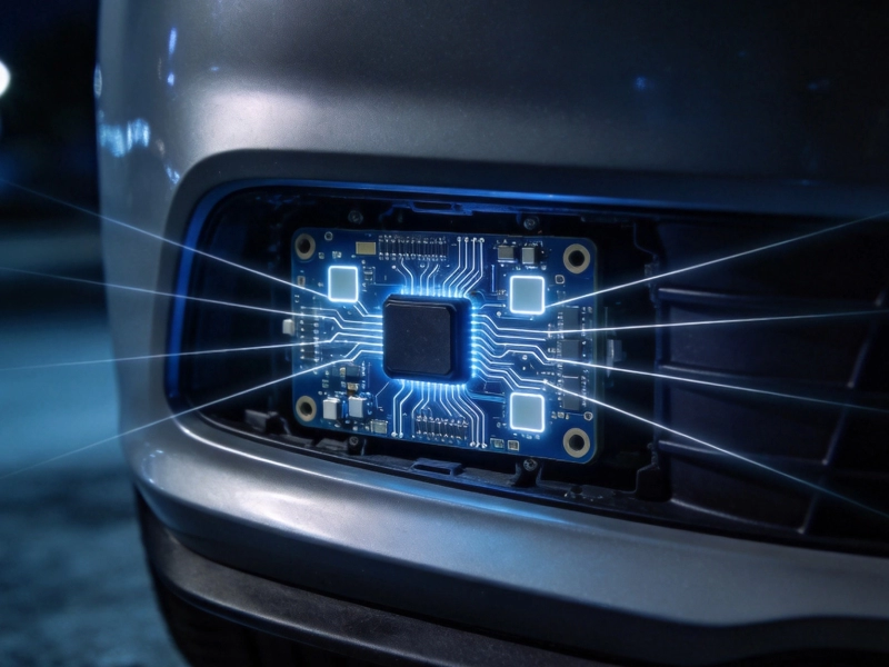
Hydrocarbon ceramics like Rogers Ro4003c and RO4350B have Dk values of 3.38 and 3.48 respectively, with Df values of 0.0027 and 0.0037. These loss characteristics are adequate for most applications up to approximately 20 GHz, covering the vast majority of commercial RF and microwave applications including cellular infrastructure, Satellite Communications, and Automotive Radar. The hydrocarbon resin system processes more like standard FR-4 than like PTFE, which means that fabricators with standard equipment and experienced personnel can produce boards on hydrocarbon ceramic materials without the specialized processes required for PTFE.
The Dk stability of hydrocarbon ceramics is generally good across the commercial microwave frequency range, with less variation with frequency than FR-4. The thermal coefficient of Dk for hydrocarbon ceramics is typically specified in the range of -40 to -50 ppm per degree Celsius, which is better than FR-4 but not as stable as PTFE. For applications that require operation across wide temperature ranges, the thermal drift of the dielectric constant should be included in the tolerance budget for the circuit design.
Polyimide-based materials like Kapton and Apical are used for applications requiring superior thermal performance, including high-temperature aerospace applications and processes that involve multiple high-temperature reflow cycles. The electrical performance of polyimide at high frequency is generally inferior to FR-4, with higher dissipation factor and more significant frequency dependence, which limits its usefulness for pure RF performance. However, for hybrid designs that combine high-frequency circuits with high-temperature assembly processes or operating environments, polyimide may be the only viable substrate option.
BT epoxy and cyanate ester resins offer improved high-frequency performance compared to standard FR-4 epoxy, with lower dissipation factor and better thermal stability. These materials are used in high-reliability applications like military aerospace and Telecommunications Infrastructure where the combination of thermal performance and reasonable high-frequency electrical performance is needed. The cost premium over standard FR-4 is significant but less than PTFE, and the manufacturing process is compatible with standard PCB equipment for fabricators with the appropriate experience.
Liquid crystal polymer substrates represent an emerging technology for high-frequency applications, offering excellent electrical performance with low loss and stable Dk across wide frequency and temperature ranges. LCP boards can be fabricated in multilayer configurations with consistent dielectric properties and excellent dimensional stability. The manufacturing infrastructure for LCP is less mature than for FR-4 or hydrocarbon ceramics, which limits the number of qualified fabricators and increases the cost and lead time for LCP-based designs.
The glass weave reinforcement that provides mechanical strength in conventional PCB laminates creates electrical inhomogeneity that affects high-frequency performance in ways that are often overlooked. Standard PCB substrates are constructed from woven glass fiber fabric impregnated with epoxy resin. The woven construction creates a pattern of glass-rich areas where the weave bundles cross and resin-rich areas in the gaps between the bundles. These areas have different dielectric constants because glass and epoxy have different Dk values, creating a composite dielectric with spatially varying properties.
At low frequencies, the spatial variation in Dk averages out over the wavelength and does not affect circuit performance. At microwave frequencies, the wavelength is short enough that a trace may traverse only a few weave cells over its length, and the local Dk variation caused by the weave pattern causes local impedance fluctuations that create scattering and phase distortion. This effect, known as glass weave effect, is particularly pronounced for traces that are oriented perpendicular to the glass weave direction and for very narrow traces that are narrower than the weave cell dimensions.
Addressing glass weave effects requires either using spread weave glass styles that distribute the glass more uniformly, or using non-woven reinforcement materials like ceramic-filled composites that do not have the periodic structure of woven glass. The "1080" and "1078" glass styles have finer weave counts than standard "7628" style and provide more uniform resin distribution. For the most demanding applications, homogeneous materials like PTFE composites that have no glass weave reinforcement eliminate the effect entirely but at higher cost and with different mechanical properties.
Most Pcb Substrate Materials absorb some amount of moisture from the environment, and this moisture absorption affects the electrical properties of the material. Water has a Dk of approximately 80 at low frequencies, which is dramatically higher than the Dk of any common PCB substrate material. When moisture is absorbed into the substrate, it increases the effective Dk and the loss tangent, degrading the electrical performance. The effect is reversible, with the properties returning to baseline as the moisture evaporates, but for fielded products that must operate in humid environments, the baseline properties must be specified with appropriate humidity margins.
Hydrophobic materials like PTFE absorb minimal moisture, typically less than 0.02% by weight, which makes them ideal for humid environments or outdoor applications where moisture exposure is expected. Epoxy-based materials like FR-4 and hydrocarbon ceramics absorb more moisture, typically 0.1 to 0.3%, which causes measurable changes in Dk and Df when the material is humid. The absorbed moisture also affects the dimensional stability and the breakdown strength of the dielectric, creating reliability concerns for high-voltage applications in humid environments.
Conformal Coating or encapsulation can protect the board from moisture absorption but may introduce its own electrical effects if the coating material has different dielectric properties than air. For high-frequency circuits, the coating dielectric changes the effective Dk around traces and can detune circuits that were designed for air as the surrounding medium. The coating material and thickness must be included in the electrical model if coating is planned for circuits operating above approximately 5 GHz.
The dielectric constant of a PCB substrate is not perfectly consistent from lot to lot or even within a single lot. The Dk tolerance of standard materials like FR-4 is typically specified as +/- 0.1 or larger, which at high frequencies translates to impedance tolerances that may be unacceptable for controlled-impedance designs. High-performance microwave materials typically have tighter Dk tolerances, with some PTFE composites specified to +/- 0.02 or better, but even these tight tolerances can cause problems for the most demanding narrowband circuits.
The Dk tolerance affects both the impedance accuracy and the frequency accuracy of resonant circuits. For a Microstrip filter with tight passband specifications, the Dk tolerance directly translates to passband frequency variation that may cause the filter to fail its specification. For a 50-ohm controlled-impedance trace, the Dk tolerance translates to impedance variation that must be accounted for in the tolerance budget. Designs that require tight Impedance Control may need to specify a particular lot of material or require incoming Dk verification to ensure the material Dk is within the required range.
Some fabricators offer Dk testing services that measure the actual Dk of the manufactured board using techniques like the differential phase length method or cross-waveguide measurement. This testing adds cost but provides direct verification that the electrical properties of the delivered boards meet the design requirements. For high-volume production of sensitive Rf Circuits, the cost of Dk testing may be justified by the yield improvement and the reduced risk of field failures due to material property variation.
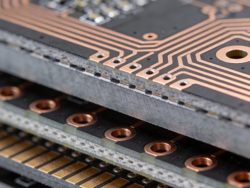
High-frequency circuits often dissipate significant power, particularly in power amplifier applications, and the thermal properties of the substrate affect how efficiently heat is removed from the active devices and the transmission lines. The thermal conductivity of Pcb Substrate Materials ranges from approximately 0.3 W/mK for standard FR-4 to 1.0 W/mK or higher for ceramic-filled materials. The higher thermal conductivity of ceramic-filled composites helps spread heat from hot spots and reduces the temperature rise of the substrate under load.
Metal-backed substrates, where a metal plate is bonded to the dielectric substrate, dramatically improve thermal performance by providing a high-conductivity path for heat flow away from the active circuitry. Metal core PCBs using aluminum or copper backing are commonly used for high-power RF amplifiers, motor drives, and LED lighting applications where Thermal Management is the primary constraint. The metal backing changes the electrical environment of the transmission lines because the metal provides a second reference plane that affects impedance and wavelength, which must be accounted for in the electrical design.
The thermal expansion coefficient of the substrate material must be matched to the thermal expansion of the metal components, including the copper conductors and any plated through-holes. Mismatch in thermal expansion creates mechanical stress during temperature cycling that can crack vias, delaminate copper, or shift component positions. High-temperature materials like polyimide and BT epoxy have better thermal expansion matching to copper than standard FR-4, which makes them preferable for applications with wide temperature ranges or multiple thermal cycles during assembly and use.
The material selection decision for a High-frequency Pcb should be driven by the specific requirements of the application rather than by a generic "best performance" criterion. The key parameters to evaluate are the operating frequency range, the loss budget, the impedance tolerance, the temperature range, the humidity environment, the mechanical requirements, and the cost target. Matching these requirements to the available material options identifies the lowest-cost material that meets all the application requirements.
For applications below 5 GHz where loss is not critical and cost is the primary driver, standard FR-4 or the less expensive hydrocarbon ceramic composites like RO4003C are appropriate choices. These materials are widely available, easy to manufacture, and cost-effective for the performance level they provide. The Dk tolerance and loss performance may limit their usefulness for narrowband or high-Q designs at the upper end of this frequency range, but for broad bandwidth or moderate-Q designs, they are usually adequate.
For applications from 5 to 20 GHz, hydrocarbon ceramic composites like RO4350B are the workhorse choice, offering a good balance of electrical performance, mechanical processability, and cost. These materials handle most commercial wireless infrastructure, Automotive Radar, and instrumentation applications effectively. For the most demanding applications in this range that require the lowest loss or the tightest Dk tolerance, PTFE-based materials may be necessary despite their higher cost and more complex manufacturing requirements.
For applications above 20 GHz, PTFE-based materials are generally necessary to achieve the required electrical performance. The exceptional low-loss properties of PTFE composites are essential for millimeter-wave applications where even small losses accumulate over the wavelength-scale dimensions of the circuit. The higher cost and manufacturing complexity of PTFE are accepted as the price of achieving the required performance in this frequency range.
High-frequency Pcb Material Selection is a nuanced engineering decision that requires understanding both the electrical properties of available materials and the specific requirements of the target application. The fundamental properties of dielectric constant and dissipation factor determine the propagation characteristics and loss of transmission lines, and the frequency and temperature dependence of these properties determines whether the circuit will perform consistently across its operating range. No single material is optimal for all applications; the best choice is always a trade-off between electrical performance, mechanical and thermal properties, manufacturing complexity, and cost.
The design process for high-frequency circuits should include material selection as an early step, before the stack-up and trace geometry are finalized, because the material properties directly determine the trace dimensions needed to achieve the target impedance. Designing a 50-ohm microstrip on PTFE requires a different trace width than the same 50-ohm line on FR-4, and changing the material after the layout is complete requires reworking the trace geometries to maintain impedance. Early material selection prevents costly redesign iterations and ensures that the manufactured board matches the designed electrical performance.
Contact us to discuss your requirements and explore how our High-frequency Pcb material expertise and manufacturing capabilities can support your RF and microwave design needs.
The Ultimate Guide to High Frequency PCB Materials: PTFE, Ceramic, and HydrocarbonJuly/08/2026

Top 5 High Frequency PCB Materials for 5G Base Station ApplicationsJuly/30/2026
The Impact of Copper Foil Type on High Frequency PCB Materials PerformanceSeptember/16/2026
Emerging Trends in High Frequency PCB Materials for Next-Gen CommunicationOctober/10/2026
High Frequency PCB Material Selection: Dk, Df, and Loss ConsiderationsNovember/05/2026
High Frequency PCB Materials for Automotive Radar: Durability and SpeedSeptember/26/2026
Choosing the Right High Frequency PCB MaterialsMay/29/2026
Understanding Thermal Stability in High Frequency PCB MaterialsAugust/10/2026