Open Nav

If you've ever designed a circuit that operated at microwave frequencies, you quickly discover that Fr-4—the ubiquitous PCB substrate that works perfectly well for most digital circuits—starts to misbehave in ways that are hard to ignore. Your insertion losses are higher than expected. Your signal propagation velocity varies with frequency in ways that distort your waveforms. Your carefully matched networks drift with temperature. These aren't symptoms of a bad design; they're symptoms of using the wrong substrate material. At RF and microwave frequencies, the dielectric properties of your PCB material matter as much as your circuit topology.
The electronics industry has developed a range of high-frequency laminate materials specifically designed for these applications. Understanding what these materials offer—and when you need them—helps you make better choices for your RF designs and avoids the disappointment of boards that work beautifully in simulation but poorly on the bench.
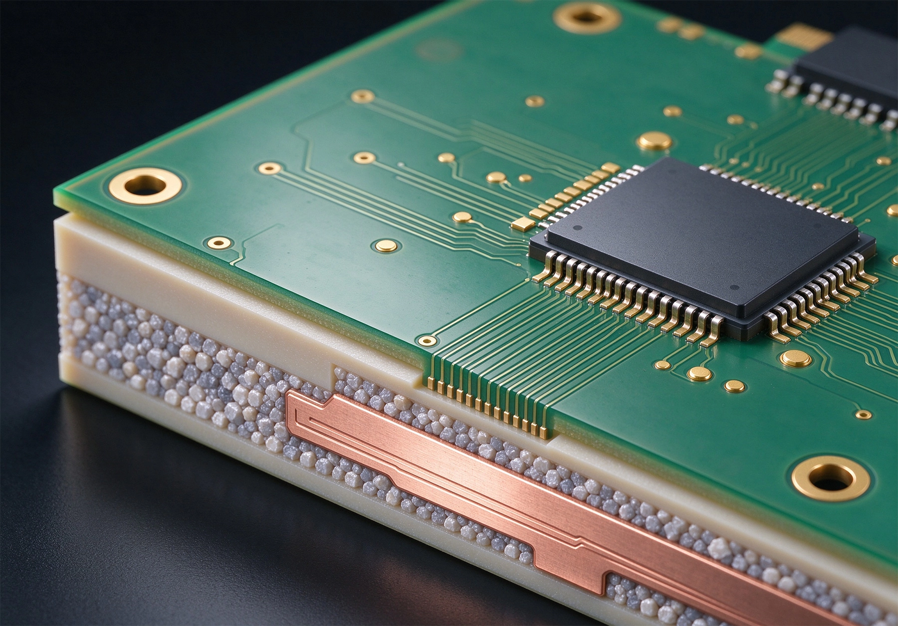
Fr-4 is a glass-reinforced epoxy composite that has served the electronics industry well for decades. It's inexpensive, widely available, mechanically robust, and electrically adequate for most digital applications. But its dielectric properties—specifically the Dissipation Factor and Dielectric Constant stability—are optimized for lower frequencies where these parameters matter less.
At frequencies above a few gigahertz, FR-4 starts to show significant dielectric losses. The Dissipation Factor (Df), which measures how much electrical energy is lost as heat in the material, becomes substantial enough to reduce signal strength noticeably. A Transmission Line on FR-4 might lose 3 dB or more per inch at 10 GHz—completely unacceptable for many RF applications.
The Dielectric Constant (Dk) of FR-4 also varies with frequency and temperature in ways that create problems. If your Dk changes with frequency, your propagation velocity changes, which distorts signals and makes Impedance Control difficult. If Dk changes with temperature, your circuit performance drifts as the board heats up during operation. For precise RF work, you need a material with stable, predictable dielectric properties.
High-frequency laminates address the specific failure modes of FR-4 at RF and microwave frequencies. They offer lower dissipation factor for reduced losses, stable dielectric constant across frequency and temperature ranges, and consistent material properties batch to batch for reproducible designs. The trade-off is cost—these materials are significantly more expensive than FR-4, and they require different manufacturing approaches.
Polytetrafluoroethylene, better known by the brand name Teflon, forms the basis of many high-frequency laminate materials. Ptfe has exceptional electrical properties: very low dissipation factor, stable dielectric constant, and excellent high-frequency performance. The challenge is that Ptfe is mechanically challenging to work with compared to epoxy-based materials.
pure PTFE laminates without reinforcement offer the best electrical performance but are soft and dimensionally unstable. They compress under pressure, flow at high temperatures, and require special handling during drilling and routing. These materials are rarely used as-is for production boards because the manufacturing difficulties outweigh the electrical benefits.
For applications requiring the absolute lowest losses, some designers still specify pure PTFE, accepting the manufacturing challenges in exchange for the best possible electrical performance. This is most common in aerospace and defense applications where performance justifies the cost and complexity.
The practical solution is to combine PTFE with woven glass reinforcement, which provides mechanical strength and dimensional stability while preserving much of PTFE's electrical performance. These composites are the workhorses of high-frequency PCB Fabrication, available from multiple suppliers in various formulations optimized for different frequency ranges and applications.
Glass-reinforced PTFE laminates are available in a range of dielectric constants, from around 2.1 to 10.2, allowing designers to choose the material that best suits their impedance and routing requirements. Thicker laminates with lower dielectric constants support wider traces for a given impedance, while thinner laminates with higher dielectric constants allow more compact designs.
Ceramic-filled PTFE composites represent another approach to optimizing high-frequency materials. By mixing ceramic particles into the PTFE matrix, manufacturers can achieve higher dielectric constants than pure PTFE while maintaining reasonable mechanical properties and improving thermal conductivity compared to glass reinforcement.
The ceramic fillers also help with dimensional stability and reduce the coefficient of thermal expansion in the z-axis, which improves reliability for boards with plated through holes. These materials have become popular for applications like patch antennas and RF power amplifiers where the combination of high dielectric constant and low loss is valuable.
Rogers Corporation is the dominant supplier of high-frequency laminates, with a product line that covers the full range of RF and microwave applications. Their materials are so widely used that "Rogers" has almost become a generic term for high-frequency Pcb Materials, much like "Kleenex" for tissues.
The RO4000 series represents Rogers' most popular product line for commercial RF applications. These materials use a hydrocarbon ceramic填充体系 rather than PTFE, which makes them easier to process using standard FR-4 manufacturing equipment. The RO4003C and RO4350B are probably the most widely used materials in this series.
RO4000 materials offer low loss characteristics that are excellent for most commercial RF applications up to 20 GHz or so, with dielectric constants around 3.4 to 3.5. They can be processed with standard FR-4 workflows for drilling, plating, and routing, which dramatically reduces manufacturing complexity and cost compared to PTFE-based materials.
The trade-off is slightly higher loss than PTFE materials and less stable dielectric constant over temperature. For commercial applications like cellular infrastructure, Wi-Fi equipment, and Automotive Radar, RO4000 series materials usually provide the best balance of performance and manufacturability.
The RO3000 series uses ceramic-filled PTFE specifically designed for high-dielectric-constant applications. Available in versions with dielectric constants of 6.15, 10.2, and 11.2, these materials are used for applications where the high Dk enables smaller antenna elements, tighter coupling between traces, or reduced board size.
Patch antenna designs particularly benefit from RO3000 materials because the high dielectric constant allows smaller antenna patches for a given frequency. The trade-off is that higher Dk also means tighter manufacturing tolerances for Impedance Control and potentially more sensitivity to moisture absorption.
RT/duroid represents Rogers' PTFE-based materials for the most demanding applications. These materials offer the lowest losses and most stable electrical properties but require specialized processing that differs significantly from standard Pcb Manufacturing. RT/duroid materials are specified for aerospace, defense, and test equipment applications where performance margins are critical.
Building multilayers with high-frequency core materials is more complex than with standard prepreg. Rogers developed the ULW (ultra-low profile woven) series specifically for multilayer constructions, with materials designed to bond well to Rogers core materials and to standard FR-4 prepreg where needed.
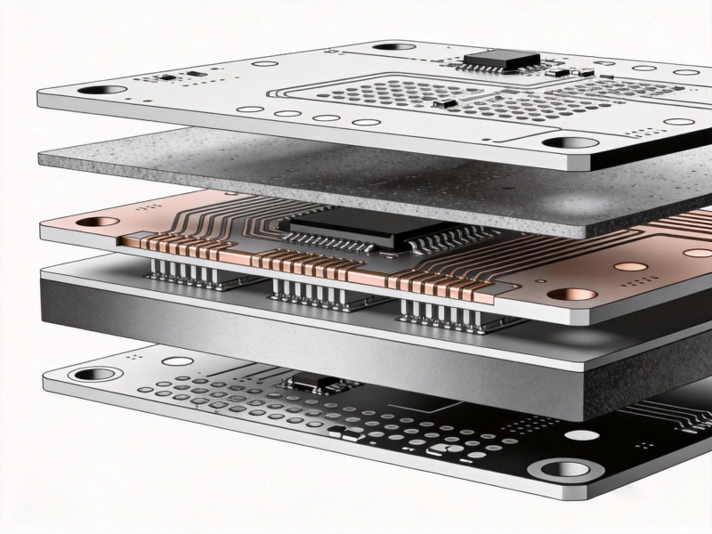
Multilayer high-frequency boards often use a Hybrid Stackup with Rogers materials for the RF layers and FR-4 for the digital layers. This approach optimizes cost by using expensive high-frequency material only where it's actually needed, while the FR-4 layers provide mechanical structure and accommodate through-hole vias for the digital circuitry.
Rogers dominates the high-frequency laminate market, but several other suppliers offer competitive products. Understanding the alternatives helps you evaluate options and potentially find better value for your specific application.
Isola produces a range of high-frequency materials including the I-Speed and I-Mile families. These materials target the mid-range of the high-frequency market, offering good performance at lower cost than Rogers materials. For applications where extreme performance isn't required, Isola products provide a cost-effective alternative.
Taconic offers PTFE-based and hybrid materials under brand names like RF-35, TLX, and TLY. Their product range covers both low-dielectric-constant materials for Transmission Lines and higher-Dk materials for antenna applications. Taconic materials are widely used and generally well-regarded in the industry.
ARLON was a significant competitor to Rogers before being acquired by Rogers Corporation. Their product lines, including the TC600 and AR400 series, continue to be available under the Rogers umbrella. For existing designs that specify ARLON materials, production can continue using the same specifications.
When evaluating high-frequency materials, several electrical and mechanical properties deserve attention. Understanding what each property means for your application helps you make informed material selections.
The dielectric constant determines how the material affects signal propagation velocity and trace width requirements for a given impedance. Lower Dk materials allow faster signal propagation and require wider traces for the same impedance. Higher Dk materials enable more compact designs but have slightly higher losses in some configurations.
For most Transmission Line applications, a Dk between 3 and 4 works well. For antenna applications where size reduction is valuable, Dk values of 6 or higher might be worth considering despite the trade-offs.
Dissipation factor directly affects Insertion Loss at high frequencies. Lower Df means less energy lost as heat. PTFE materials typically have Df values around 0.0005 to 0.001. Rogers RO4000 series materials are around 0.003 to 0.004. Standard FR-4 might be 0.02 or higher at microwave frequencies. The improvement from FR-4 to high-frequency materials can be an order of magnitude or more.
TCDk measures how much the dielectric constant changes with temperature. Lower TCDk means more stable performance as the board heats up during operation. This is particularly important for outdoor or automotive applications where boards might see wide temperature ranges during normal operation.
Some high-frequency materials absorb moisture more readily than others, and moisture affects dielectric properties. PTFE-based materials generally have very low moisture absorption, while ceramic-filled materials might absorb more. If your application will see humid environments, moisture sensitivity should factor into your material selection.
High-frequency materials require different manufacturing approaches than standard FR-4. Understanding these requirements helps you work effectively with your manufacturer and avoid surprises during production.
PTFE materials are challenging to drill because the material is soft and tends to smear rather than form clean holes. Special drill geometries and processing parameters are required, and some manufacturers use plasma cleaning instead of chemical desmear to prepare PTFE vias for plating. These differences add cost and may affect minimum via sizes.
RO4000 series materials, because they use a hydrocarbon ceramic system rather than PTFE, can generally be processed with standard FR-4 drilling parameters. This is a significant advantage for manufacturing efficiency and cost.
Achieving good copper adhesion on high-frequency materials requires surface preparation steps that differ from FR-4. Standard oxide treatments don't work well on PTFE, so alternative approaches like plasma treatment or specialized chemical processes are used. The surface finish selection also matters—some finishes adhere better than others on high-frequency substrates.
High-frequency circuits usually require tight impedance control, which means tighter manufacturing tolerances on trace widths and laminate thickness. Your manufacturer needs to have the process control and measurement capabilities to achieve the tolerances your design requires. This often means more extensive testing and potentially using impedance-coupled test coupons to verify performance.
Material selection for high-frequency PCBs involves balancing electrical performance, manufacturability, cost, and reliability. Here are some guidelines for common application categories.
Base station and small cell equipment operating at 1 to 6 GHz typically uses Rogers RO4000 series or equivalent materials from other suppliers. The frequency range and power levels are well-matched to these materials, and the volumes are high enough to justify the material cost. The ability to process RO4000 with near-FR-4 workflows keeps manufacturing costs manageable.
77 GHz and 24 GHz Automotive Radar systems push the frequency range high enough that material selection becomes even more critical. Rogers RO3003 or equivalent Low-loss Materials are typically specified. The reliability requirements for automotive applications also drive toward materials with proven automotive qualification and consistent lot-to-lot properties.
Wi-Fi equipment at 2.4 GHz and 5 GHz can often use RO4000 series materials successfully, with cost being the primary driver of material selection. For high-volume consumer products, even small per-board material cost differences compound into significant total cost differences, making material optimization important.
Space and aerospace applications demand the most stable and reliable materials, often specifying RT/duroid or equivalent products from other suppliers. The Extreme Environment—vacuum, radiation, thermal cycling—requires materials with proven space heritage and extensive qualification testing. Cost is secondary to performance and reliability in these applications.
High-frequency materials are expensive, but several strategies can help manage costs without sacrificing essential performance.
Using Rogers or other high-frequency materials only for the RF layers while using FR-4 for digital layers minimizes expensive material usage. The FR-4 layers handle through-hole vias, power distribution, and lower-frequency signals, while the high-frequency layers are reserved for the actual RF circuitry.
Don't over-specify your material requirements. If your application operates at 5 GHz with moderate power levels, you probably don't need the absolute lowest-loss material available. A mid-range high-frequency material might provide adequate performance at significantly lower cost. Match your material selection to your actual frequency, power, and loss requirements.
Work with your manufacturer to optimize panel utilization for high-frequency materials. Because these materials cost more per square foot than FR-4, inefficient panel utilization significantly impacts total cost. Designing boards that fit efficiently on standard panel sizes and that can be nested well improves material utilization.
High-frequency Pcb Materials solve real problems that FR-4 cannot address at RF and microwave frequencies. The dissipation factor and dielectric constant stability of materials like Rogers RO4000 series or PTFE-based laminates enable designs that simply wouldn't work on standard substrates.
Rogers materials dominate the market because they offer good to excellent performance across a wide range of applications. The RO4000 series provides the best balance of performance and manufacturability for most commercial RF applications. For more demanding requirements, RT/duroid and RO3000 series materials offer higher performance at correspondingly higher cost and complexity.
PTFE-based materials provide the lowest loss but require specialized manufacturing processes. If your design truly needs that last fraction of a dB of loss improvement, PTFE might be worth the manufacturing complexity. For most applications, hydrocarbon ceramic materials like RO4000 provide sufficient performance with standard manufacturing workflows.
Material selection should match your actual requirements. Don't specify exotic materials for applications where mid-range high-frequency laminates would work perfectly well. The cost savings from appropriate material selection can be significant in high-volume production.
Contact us to discuss your High-frequency Pcb material requirements and find the best solution for your specific application.
Hybrid Stack-ups: Combining FR4 and RF Materials in High Frequency PCB FabricationSeptember/14/2026
Environmental Considerations in Sustainable High Frequency PCB FabricationSeptember/23/2026
Overcoming Delamination Challenges in Multilayer High Frequency PCB FabricationJuly/28/2026
What Is a High Frequency PCB and When Do You Need One?October/19/2026
High Frequency PCB Fabrication: Managing Dielectric Constant (Dk) TolerancesJune/09/2026
High Frequency PCB Fabrication with Rogers and PTFE Materials: A Technical GuideJuly/16/2026
Advanced High Frequency PCB Fabrication Techniques for Low Loss PerformanceMay/29/2026
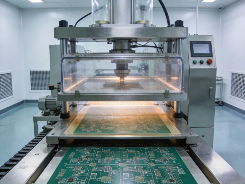
The Role of Vacuum Lamination in High Frequency PCB FabricationAugust/07/2026